Torque-compliant rotor for collective control
Introduction to concept
This project concerns itself with developing a helicopter rotor that can automatically enter autorotation. Most helicopters transition between powered by and unpowered flight through active control inputs from the pilot. The blades are set at a positive pitch angle in powered flight to produce lift. The blades are set to a much lower or negative pitch angle in autorotation to generate lift.
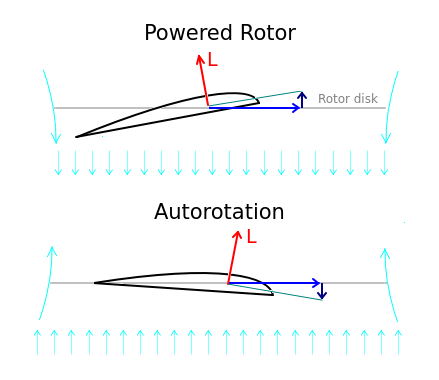
These changes in pitch can be accomplished automatically by using the torque acting on the rotor to dictate the pitch it requires to ensure lift. This is because, in powered flight, the rotor absorbs torque applied to it by a motor, while in autorotation, it is spun by the lift of the blades and there is little to no torque. This asymmetry in torque allows one to differentiate between both states.
It must be mentioned that much of this project is inspired by the simplicity of the rotor of a radio-controlled autogyro. It is nothing more than a strap bolted onto a bearing housing in its simplest case. The blades attach to the strap, and cyclic pitch is accomplished by bending the strap. For part of the cycle the strap bends, and for the remaining half, it pitches the blades.
 See: RC Autogyro - Panther build diary
While an autogyro does not need collective pitch to fly, a helicopter greatly benefits from this ability. It allows the helicopter to rapidly change lift and allows the rotor to transition from powered (positive pitch) and unpowered (little or negative pitch) flight. This is generally accomplished through a swashplate controlling the blades.
As can be inferred, a helicopter rotor with cyclic and collective is far more complex than the flexplate used by an autogyro. Evidently, it is very appealing to modify the flexplate design to include collective control while maintaining its simplicity.
Initial design concept
The concept is to use the torque acting on the rotor to change the pitch angle of the blades. When the motor is on, it applies torque to the rotor and rotates the blades to a positive pitch. When the motor shuts off, there is no torque and the blades return to negative pitch for autorotation. An important inspiration for this concept is the underactuated rotor developed at the University of Pennsylvania:
Video 1. Underactuated rotor cyclic
While this design is intended for cyclic pitch, the idea is valid for collective control. Mainly, one can exploit motor torque to pitch the blades. For cyclic control, the torque that causes the blades to lead and lag is the relative inertia between the blades and the motor. The motor accelerates faster than the blades, and this causes the blades to rotate relative to the skewed hinges. However, centrifugal forces resist this relative rotation, and the motor reaches an equilibrium deflection.
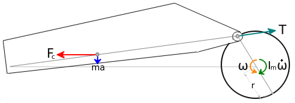
Unfortunately, the skewed hinge used for cyclic control will not work for collective pitch. In this case, the force driving the lag of the blades is aerodynamic drag. Ideally, this force is kept very small to minimize the power drawn by the rotor. Consequently, the scant drag force barely deflects the blades as centrifugal force is much larger.
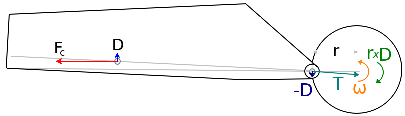
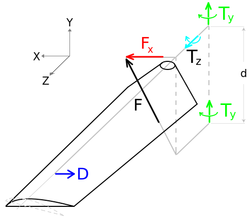
The solution for the lack of deflection is to amplify the torque generated by drag. Even if the drag is small, it can still generate a large torque with an adequate mechanical advantage. A simple approach is to use a conrod connected to a lever that twists the blades. By making the effective lever arm longer, the force acting on the conrod is amplified, and this greater force generates a larger torque on the blade.
Design iterations
Iteration 1:
The first version of the helicopter did not have a collective pitch. Rather, the blades were set at a positive pitch and rotor RPM was changed to control altitude. This allowed the rotor to be very simple and let the aircraft’s flight characteristics to be fine-tuned. Mainly, to identify the aircraft’s stability and controllability about all three rotational axes. The yaw axis was expected to have robust control as it worked by changing the speed of a lightweight propeller. However, the pitch and roll axes were ambiguous as a gimballed rotor has a delayed response.
Video 2. Fixed pitch rotor
Upon testing the aircraft, it was obvious augmented stability was necessary. Once this was added, the helicopter was quite controllable, although still with a noticeable lag in its controls. Despite this, it was possible to fine-tune the flight controller to achieve adequate control, both in hover and in forward flight.
Iteration 2:
The second iteration of the aircraft employed a self-adjusting rotor. The first version of the rotor was extremely simple and used string instead of conrods to transfer loads. While this worked, it placed large torque loads about the flexible strap carrying the blades. Nonetheless, while the load distribution left much to be desired, it did prove that a torque-compliant rotor was feasible.
Video 3. Initial test of concept
Upon test flying the aircraft, it became obvious that altitude control was much faster. Collective changes allowed the aircraft to respond without the lag the rotor accelerating. Moreover, since the collective increased with motor torque, the rotor tended to maintain a similar RPM as the changes in pitch acted like a governor in a constant speed propeller.
Iteration 3:
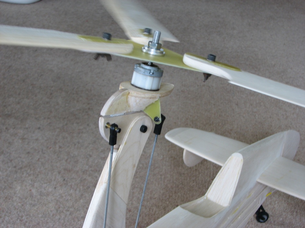
The next iteration of the aircraft refined the rotor design by replacing the strings with rigid linkages and adding ball bearings. While it was more complex, the modifications made adjusting the blade tracking much easier. This reduced vibrations from the rotor.
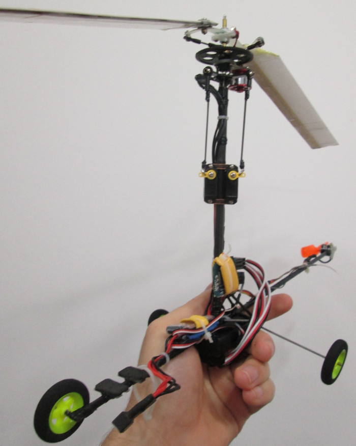
Overview of the aircraft
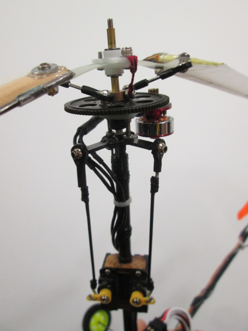
Side view of the rigid linkages
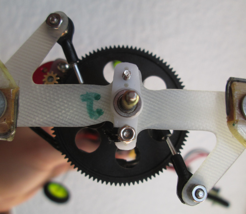
Closeup of the rigid linkages
Video 4. String replaced with rigid linkages
Iteration 4:
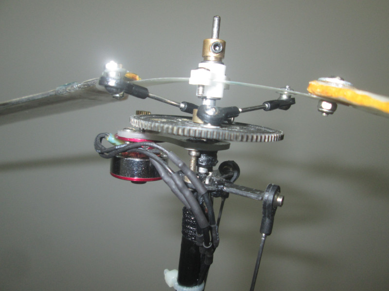
At this point, the torque-compliant rotor had been shown to work and all that was left was to improve the cyclic. The apparent lag was caused by the aircraft accelerating slowly for a given input. The acceleration could be increased by two means: reducing the moment of inertia, or increasing the distance between the rotor thrust vector and the center of mass. The airframe was rebuilt to incorporate these changes. To this end, the servos were placed at a lower position on the rotor mast, the rotor mast was extended, and the electronic components were grouped near the bottom of the mast.
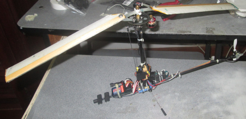
Left view of the improved airframe
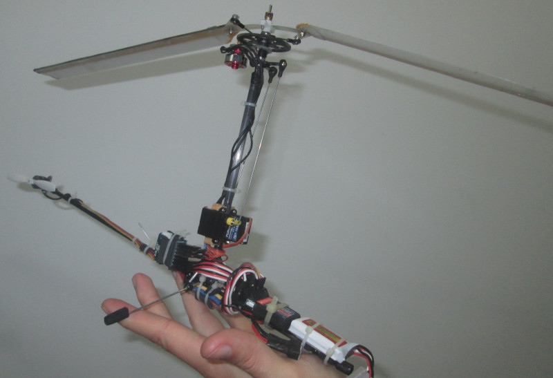
Right view of the improved airframe
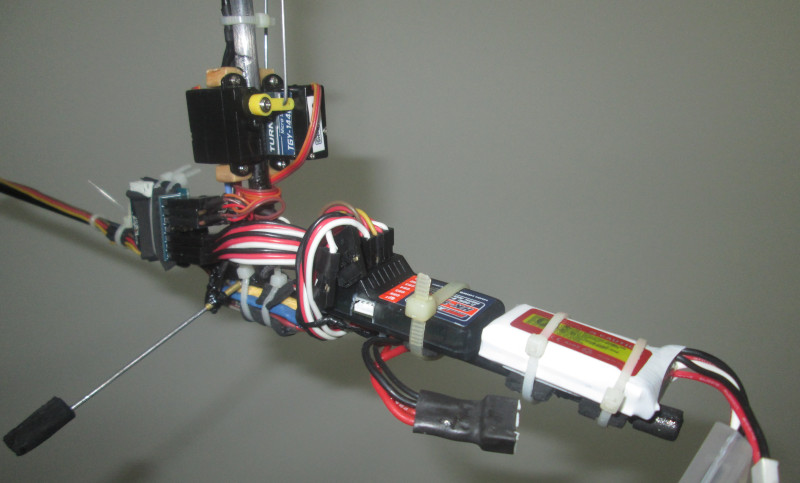
Closeup of the electronics
Besides a new airframe, the rotor was modified to have the conrods push rather than pull the rotor. This improved the loads on the conrods as the threads inside the sockets did not resist tension loads. The modification also changed the way the blades twisted. As the pitch increased, the conrods had a smaller angle relative to the lever arm connected to the blade. The resulting feedback loop naturally limited the maximum pitch of the blades.
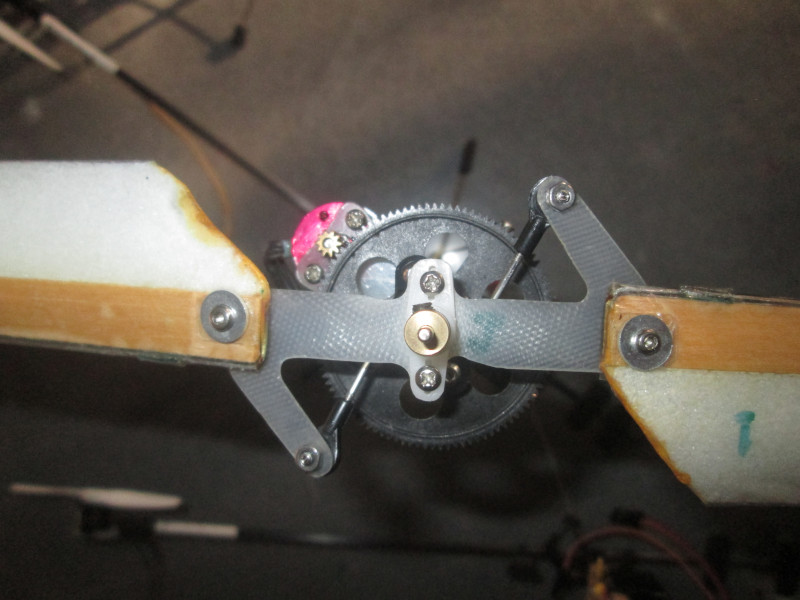
Top view of the reversed linkages
Side view of the reversed linkages
Video 5. Second iteration of the rotor
Overall, these changes improved the performance of the helicopter. The cyclic control was noticeably faster and rotor vibrations were reduced. While control response was not as fast as a helicopter with a swashplate, it was still acceptable for all flight conditions.
Video 6. Flight performance of the improved rotor
After the helicopter was tuned to achieve flight, its ability to autorotate was investigated. This involved piloting the aircraft to a large altitude and shutting off the motor. As expected, the aircraft transitioned smoothly into autorotation. The rotor kept spinning and the aircraft settled into a steady-state descent. Unfortunately, friction from the motor caused the fuselage to rotate during autorotation. The tail rotor could not stop the rotation as it could only apply force in one direction.
Video 7. Demonstration of auto-rotation
Given this behavior, future iterations of the aircraft should include a large vertical stabilizer. While this will not prevent the aircraft from rotating in vertical descent, it will stop the rotation with modest forward velocity. This is beneficial as the additional airspeed will decrease the descent rate.