Flight controller for a weight-shift RC helicopter
Introduction to concept
Helicopters are naturally unstable aircraft. Without a system to augment their stability they will inevitably spiral towards the ground. Thankfully, theres a few ways to enhance their stability. A classic approach is to use a heavy bar placed at an angle relative to the rotor blades. Such a system is known as a flybar, stabilizer-bar, or mechanical gyro.
This system works by exploiting the angular momentum of the bar. When disturbed, the bar will tend to stay rotating about its current plane. This “resistance” to changes in orientation can fed to the rotor blades to damp the rotation. There are many examples of this stabilization system, be it in large manned helicopters or in small radio-controlled models. Here is a video of what the bar’s motion looks like on a small rc-helicopter:
For helicopters with more than two blades, the bar transforms into a star-shaped object or a ring.
While this system works, it comes at the cost of increased mechanical complexity. One can side-step this issue by using electronics to provide analogous control inputs. This greatly simplifies the rotor head but it transfers the complexity to an electronic circuit. With the onset of cheap microcontrollers, this complexity can be abstracted away and emphasis can be placed on the control algorithm.
Project overview
This project concerns itself with the development of a simple and lightweight flight controller for an RC helicopter. To keep things simple, it will use an Arduino Nano as a development board. It only weighs around 5 grams and is just a few centimeters in length so its an ideal platform. It will also use the MPU-6050 gyroscope/accelerometer to measure the state of the aircraft. This sensor is ubiquous and inexpensive.
Stabilization Algorithm
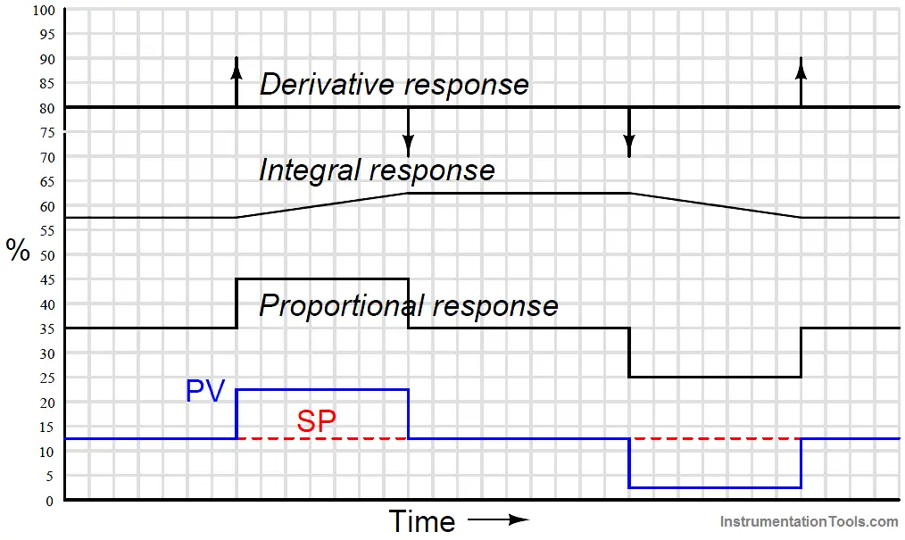
The pitch and roll axes of the helicopter can be stabilized by means of two PID Controllers. The angular velocity, as measured by a gyroscope, acts as the proportional term of the control loops. By taking time integral of this value, one obtains the angular deflection of the aircraft. Hence, the proportional term will act like a viscous damper, while the integral term will act like a spring. The derivative term would represent the angular acceleration of the aircraft, although in practice may be used to smoothen in the proportional term.
The yaw axis is different as it is affected by the torque generated by the rotor, and this in turn depends on the configuration of the helicopter. For an aircraft with a tail rotor, the yaw axis can use a PID controller along with a counter-torque term that increases with throttle. This is known as revo mixing.
These corrections can improve the short-term stability of a helicopter, but their effect on long-term stability is less clear. Nonetheless, it is not critical that the aircraft finds an upright attitude on its own. It can still be unstable so long it occurs slowly. This way the pilot can provide nessesary corrections and the helicopter can remain aloft.
Design iterations
Iteration 1:
The first version of the helicopter did not have augmented stability. Rather, the focus was on building an aircraft capable of flight and then improving its stability electronically. To this end, the aircraft used very heavy tip weights at the ends of the blades to dampen its rotation. While this worked, it caused the pitch and roll control to have a large delay. This slow response was not very detrimental in high-speed flight, but it did make the aircraft challenging to fly in a hover. Moreover, the tip weights did not enhance the long-term stability of the helicopter. All they did was slow down the motion so that a person could correct the instability.
Video 1. Passive stability
Initial airframe with heavy tip weights
Iteration 2:
The second iteration of the controller focused on implementing the basic functions needed for the device to work. These were divided into three categories:
- The PWM signals sent by the receiver could be decoded accurately and without delay.
- Information from the gyroscope could be retrieved and calibrated consistently.
- Each axis had a corresponding PID controller that combined the receiver and gyroscope signals.
While these functions were programmed succesfully, in practice it became evident that vibrations were a serious problem. The gyroscope was sensitive to the slightest disturbances, so any vibrations were measured by the sensor. As the PID controller amplified these signals, the noise would cause the controls of the helicopter to jitter. This made it impossible to make the gains large enough to achieve stable flight, as vibrations overshadowed the slower rotation of the vehicle.
To overcome this problem, a simple first order low pass filter was used to suppress the vibration noise. While this helped, it did not provide sufficient suppression. A straight forward, albeit naive, solution was to cascade multiple 1rst order filters. This increased the noise suppression but came at the cost of a larger response delay.

Unfortunately, this lag caused the PID controller to become unstable as they would not react in synch with the aircraft. This was especially noticeable with the proportional term. Therefore, tuning the filters became a compromise between noise supression and PID stability. After a lot tweaking it was possible to obtain a compromise between filter gain and PID gains. While it worked, the results were generally unsatisfactory as it left the helicopter marginally stable.
Video 2. Cascaded 1rst order filters
Helicopter with Arduino nano and MPU-6050 gyro
Iteration 3:
The third iteration focused on improving the low pass filter. It was critical to increase the filter order without increasing the delay. A digital infinite impulse response filter was a simple way to achieve this. These filters are nothing more than the sum of past signal values multiplied by coefficients. Since the coefficients are hard to calculate, the Iowa Hills IIR filter designer was used to find the values. The coefficients were then copied into the arduino code. Since the code used arrays to store the coefficients and signal values, it was trivial to try out different configurations.
The filter performed best when configured as a Chebychev filter. This provided the best compromise between noise suppression and reponse delay. The step response was very underdamped but it didn’t seem to matter. Since the helicopter rotated slowly and smoothly, the ringing was too small to be noticeable.

Whatever the IIR configuration, the results were much better than with cascaded 1rst order filters. The noise suppression was stronger and the signal delay was lower. This allowed the PID gains to increase and made aircraft much more stable and easier to fly.
Video 3. Infinite Impulse Reponse filter
Iteration 4:
The forth iteration removed the IIR filter and enabled the in-built low-pass filter of the MPU-6050. This required configuring specific registers. It was trivial since this was already needed for the gyro to communicate with the arduino. At it’s lowest setting the filter performed better than any of the hand-coded filters. Like before, this allowed the PID gains to increase and improved stability.
To complement the filter, the helicopter was adjusted to reduce mechanical vibrations. Rubber grommets were added to the control linkages to remove slop, and a skid was added to the tail boom to prevent vibration. This last tweak is subtle as it worked by increasing the moment of inertia of the entire tail boom. This changed the resonant frequency of the boom and shifted it past the frequencies caused by the tail motor. As a result, the amplitude of the vibrations were greatly reduced.
Video 4. Inbuilt low-pass filter
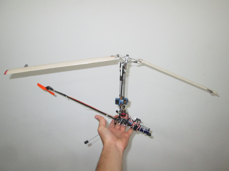
Below is the third version of the helicopter along with improved flight controller:

Overview of the helicopter

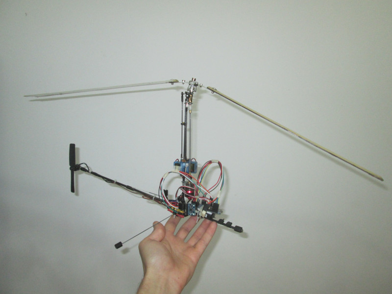
Closeup of the flight controller
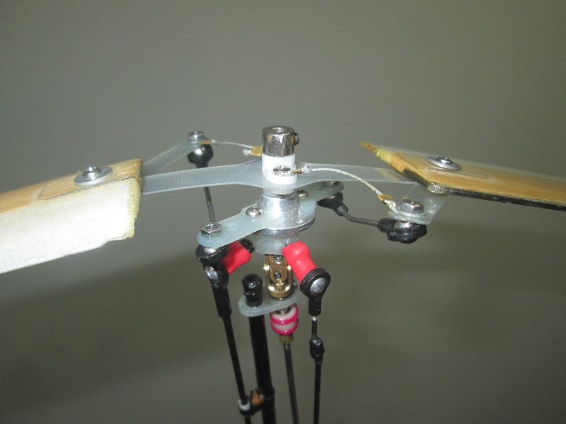
Rotor with rubber grommets
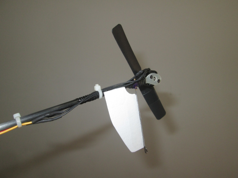
Tail rotor and heavy skid
Arduino Code
The code was designed to receive 4 PWM inputs from an RC receiver operating in MODE 2 and output 3 PWM signals. Two signals go to the cyclic servos and the third goes to a tail-servo or a speed controller. Since it is assumed only two servo motors are used for controlling the rotor, only a 90-degree swashplate is supported. See the schematic for the tail-motor variant of the required circuit:

Github Repo: HeliFlightController