Tail-less airplane stabilized by an angle of attack sensor
Introduction to concept
For an airplane to maintain stability in flight, it must have the ability to self-correct in the face of external disturbances. When this occurs, the aircraft must cause the disturbance to decrease with time. We can refine this concept by separating it into two components: static stability and dynamic stability. As the names imply, static stability is concerned with the forces acting on the aircraft in the absence of motion. That is, whether the forces acting on the aircraft reach static equilibrium and mutually oppose each other out. Dynamic stability is focused on whether the aircraft will slow down if pushed away from this equilibrium.
With these definitions, we can also notice that dynamic stability depends on static stability. Static stability ensures an equilibrium state, and dynamic stability ensures the aircraft can return to it. We can also observe an aircraft has multiple axes about which it can be stable. It can translate about three perpendicular directions, and it can rotate about these same axes:
Because the aircraft can move in six different directions, there are different ways these motions can combine to yield converging or diverging trajectories. These trajectories are known as modes of stability, and they determine the behavior of an uncontrolled aircraft. We can best understand these modes by watching them occur and then analyzing them through diagrams.
Video 1. Modes of stability
Out of these possible trajectories, let us focus on the longitudinal stability of the aircraft, and in particular, the short period mode. This mode can be understood as the “elasticity and damping” of the aircraft with respect to the angle of attack. Video 1 shows behavior at the 2:53 minute mark. This motion is caused by a restoring torque that rotates the aircraft about the pitch axis. If this torque is sufficiently strong, it will ensure that the aircraft maintains static and dynamic stability.

See: Difference between static and dynamic stability
Ultimately, it’s not important how the stabilizing torque is generated. It can be obtained by either passive or active means. Whatever the case, both methods have the same effect on longitudinal stability, but they have different effects on the lift and drag characteristics of the aircraft.
Passive Stability
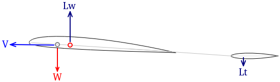
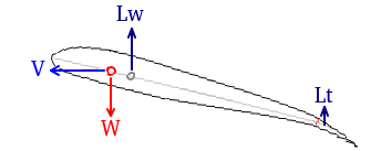
It is possible to use the aircraft’s structure and its mass distribution to induce passive stability. To accomplish this, the center of mass of an aircraft must be located infront of its center of lift. This allows the lift to have a moment arm with respect to the center of mass. The result is that whenever the angle of attack changes, the lift change tends to twist the aircraft away from the rotation. We can think of the airplane’s tendency to weathervane into the airflow. In a conventional configuration with a tailplane and a wing, this tendency is easily understood by looking at the lift acting on the tail. The more lift it produces, the more it torques the fuselage.
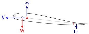
In an alternative configuration, we can move the tail forward until it merges with the wing. By doing so, we reach what is known as a reflexed airfoil. No Longer does the tail keep the nose aloft, but instead the aft portion of the airfoil provides this function.
Unfortunately, there is a large tradeoff with this configuration. Due to the upwards bent trailing edge, there is a decrease in the lift generated by the wing. This effect is worsened if the trailing edge is controlled like a flap. If the flap is raised to provide more reflex, it will generate a downwards force near the trailing edge that will rotate the airfoil to a higher angle of attack. This greater angle, in turn, forces the airfoil to produce more lift with a shape that is worse at producing additional lift.
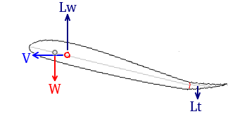
Evidently, this is a highly inefficient situation. It is especially bad during turns or low-speed flight, as the wing must operate at high angles of attack. An aircraft needs additional lift to stay aloft under these conditions. Despite these problems, a reflexed airfoil is still a viable way to stabilize an airplane.
Video 2. Demonstration of reflexed airfoil
Active Stability
The inefficiency of a reflexed airfoil can be side-stepped by moving the center of mass aft. This displacement allows the flap to be deflected downwards rather than upwards to maintain static equilibrium. Unfortunately, this configuration is unstable as the aerodynamic center is in front of the center of mass.
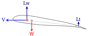
We can oppose the instability by forcing the aircraft to be stable by adjusting the rear flap. With a sufficiently large deflection, the flap can force the airfoil to rotate into the airflow, despite the front of the airfoil wanting to do the opposite.
This configuration has the advantage that the flap must deflect downward with a greater angle of attack to maintain equilibrium. The additional camber is helpful as it enhances the lift generated by the larger angle. This positive relationship is also beneficial at lower angles as it tends to increase the lift-to-drag ratio of the entire aircraft. To everyone’s advantage, there are a few examples of this kind of actively stabilized airplane available on the internet. While the details of each project vary, the underlying concept is much the same: obtain stability through active deflections of the rear flap and move the center of mass aft.
Video 3. Unstable Tailless Demonstrator
Video 4. Slope Soaring Actively Stabilized Flying Wing
See: Albatross, Active Pitch Glider
Preliminary concept
Inspired by the above aircraft, this project concerns itself with developing an actively stabilized airplane using inexpensive equipment. The design consists of two high-speed servos, an Arduino nano, a potentiometer, and a foam airframe. The potentiometer is used as an angle of attack sensor and is connected to the Arduino. The Arduino then uses this signal to control the servos connected to the control surfaces. Whenever the sensor measures a change in angle, the Arduino commands the servos to deflect the control surfaces and stabilize the aircraft.
The simplest angle-of-attack sensor is a simple low-friction potentiometer attached to a weathervane. As the weathervane will closely follow the local airflow, it can be used as a reference from which to measure the angle of attack. Likewise, the Arduino can be programmed to use the analog signal from the sensor as the proportional term of a PID controller. By adjusting the appropriate coefficients, the static and dynamic stability of the aircraft can be greatly enhanced.
Design iterations
Iteration 1:
The first version of the aircraft was designed to have passive stability. The idea was to enhance its stability electronically and use this excess stability to move the center of mass aft. This stability would make it easy to progressively move the mass and observe the behavior of the aircraft. Eventually, the mass would move aft enough to cause the aircraft to depend on the active stabilization. As a consequence, the flaps would deflect downwards to maintain equilibrium.
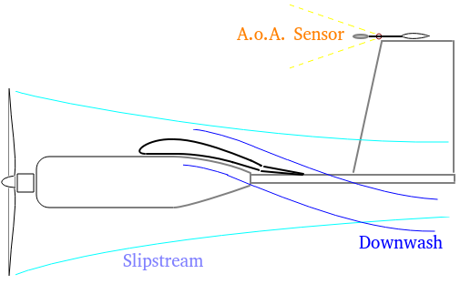
The aircraft was also equipped with a motor and a propeller to fly under its own power. However, this made it difficult to place the angle of attack sensor. The local airflow felt by the sensor is greatly affected by its location on the aircraft. Any regions behind the wing are disturbed by the large downwash, and the powerful slipstream affects anything behind the propeller. A simple solution was to place the sensor atop a long vertical stabilizer. If it were tall enough, the sensor would lie outside the propeller’s slipstream. Likewise, any lift caused by the fin would be perpendicular to the rotation of the sensor. This would minimize any effects it had on the measured angle.
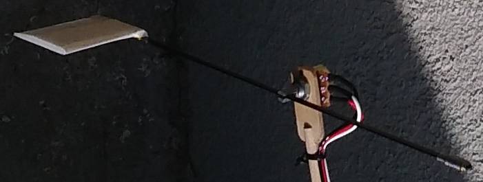
The angle of attack sensor was very simple. The weathervane was a stick with a fin in the rear and a weight in the front. It was necessary to ensure the vane was balanced about the axis of the potentiometer to eliminate any inertial effects. If this were not the case, gravity and lateral accelerations would bias the measurement. The lever arm of the vane also had to be large enough to ensure the fin could overcome the friction of the potentiometer. In order to reduce this friction, any viscous grease around the shaft of the potentiometer was removed with a solvent. This modification allowed the sensor to respond quickly to dist the airspeeds encountered in flight.
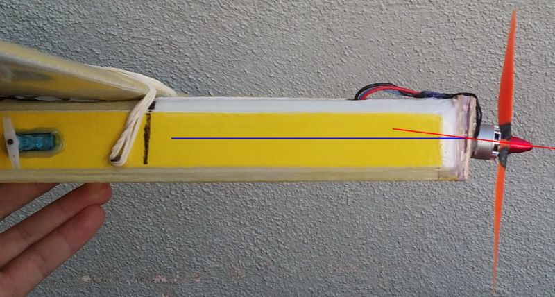
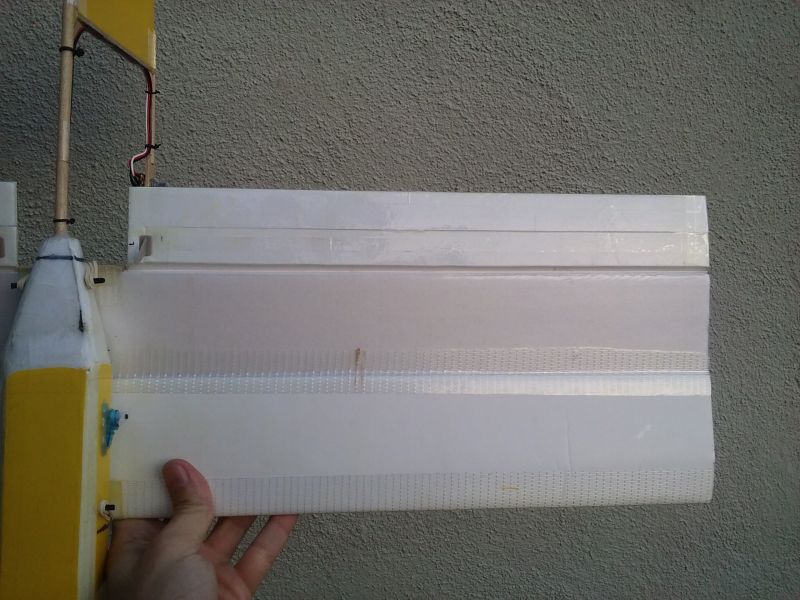
This is what the completed airplane looked like:


Unfortunately, test flights revealed the thrust line was far below the center of mass. This offset caused the aircraft to raise its nose to the point it was very difficult to recover. Secondly, the response of the elevons about the pitch axis was very sluggish and made piloting the aircraft somewhat uncomfortable. Despite this, the airplane was capable of gliding without active stabilization. This behavior indicated there was an ample margin of passive stability.
Iteration 2:
For the second iteration, the thrust line of the aircraft was rotated by tilting the firewall of the motor. Through trial and error, the motor was aligned such that the thrust did not generate a noticeable torque about the pitch and yaw axes. This was verified by running the motor at full throttle and letting the airplane enter free fall to see how it rotated.

The elevons were also made twice as large to increase the control authority and reduce lag in the control response. By extending the surfaces aft, not only did the area increase but so too did the lever arm with respect to the center of mass.

These modifications greatly enhanced the stability of the aircraft. Changes in throttle had a neutral effect on the attitude, and the pitch response was much faster. The next step was to adjust the PID controller and observe its effects on stability.
-
Proportional term: At low settings, the gain had a negligible effect on stability. The aircraft rotated more slowly for a given elevator command as the gain increased. This change made the control response slightly faster. However, after a certain amount of gain, the aircraft would shake very rapidly if it gained enough airspeed. Because of this unstable behavior, the gain was set to a value slightly below this threshold.
-
Derivative term: This had a similar effect to the proportional gain. It tended to slow down the aircraft’s rotation and made the response “crisper”. The aircraft settled to its new state with very little if any visible wobbling. Like before, the derivative gain would cause instability at higher speeds, so this threshold limited the maximum gain.
-
Integral term: Unlike the previous terms that increased the resistance to pitch disturbances, this term didn’t seem to increase the stability. Rather, the integral term did very little at low values, and at higher gains, it induced a very strong delay in the control response. This caused the aircraft to become unwieldy to pilot as prolonged inputs caused the aircraft to stay rotating for some time. Due to this delayed response, the integral term was disabled.
Having obtained a level of excess stability, it was possible destabilize the aircraft by moving the weight aft. This was done by taping a coin to the tail. Test flights showed it was only possible to shift the center of mass by a moderate amount. Beyond this point, the servos were incapable of reacting quickly enough to stabilize the aircraft. It was evident the aircraft still depended on passive stability as the flaps still had reflex while in flight.
Given this limitation, the aircraft will need to employ faster servos to eliminate its dependency on passive stability. An alternative solution is to slow down the dynamics by increasing the moment of inertia of the pitch axis. This would allow the servos slowly at the cost of a sluggish pitch response.
Arduino Code
The program used for this project was designed to receive 2 PWM inputs from an RC receiver and an analog signal, and outputs two PWM signals for two servos. It is assumed the aircraft is controlled with two elevons. It was written for an Arduino Nano but it should be compatible with other boards. It requires the PinChageInterrupt library to decode the PWM signals.
Here’s the schematic of the required circuit:

Github Repo: TailLessStability