Detect the pulse width of signals with interrupts
When working on flight controllers for radio control airplanes, I initially found it challenging to retrieve the signals generated by a hobby-grade radio receivers. These devices output pulse width modulated signals, but unlike those used to control DC motors, the actual pulse width is very small. RC receiver signals have been standardized to have a pulse width ranging between 1,000 and 2,000 milliseconds, with all of the information about the signal value encoded in the time difference between these two intervals. A signal of 1,000 microseconds is considered 0 (off), while one lasting 2,000 microseconds is 1 (on). Intermediate values represent a proportional combination of these endpoints. For example, 1,500 microseconds will be equivalent to 0.5 and so forth.
Interrupt pins
An Arduino can easily decode these signals and convert them into a floating point number by using pin interrupts for accurate timing. While polling is another option, it can quickly become ineffective and imprecise when other computations are being performed. Therefore, interrupts are the only viable choice to ensure proper timing.
See:
However, hardware interrupt pins can be problematic because they vary depending on the Arduino board. For instance, the Arduino UNO only has two interrupt pins, while all digital pins can function as pin change interrupts. This differs from hardware interrupts as pin change interrupts call a common function when there’s a state change in any of the pins the function is associated with. This requires a software solution to identify which specific pins have changed and respond accordingly.
 See:
See:
Fortunately, numerous libraries can automate this process, allowing us to assign a specific interrupt function to a particular pin without worrying about the required overhead. By utilizing one of these libraries, one can focus on decoding the individual signals sent from the radio receiver to the Arduino.
How it works
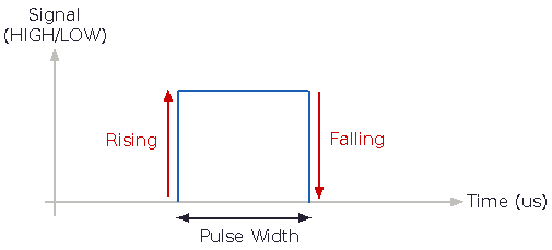
To make the necessary logic more manageable, I wrote a small library that generates a class for a single pin-change interrupt pin. These classes can then be called when assigned to a specific pin to measure the time interval of an on-and-off signal at that pin. This can be thought of as an interrupt based, non-blocking alternative to Arduino’s pulseIn function. Since it uses interrupts to measure signals, one can read multiple signals without fear of significant delays in the main loop. A pin change interrupt is used to detect when a signal is rising or falling, and the on-time of the signal is measured in microseconds. As such, this library is only suited to decode PWM-like signals, where the time of the pulse-width (on-time) determines the value of the signal.
Dependencies
This library depends on the PinChangeInterrupt library, so it works with standard Arduinos (Uno, Nano, Mega, etc) and the digiSpark ATTinys boards. Please see the documentation of PinChangeInterrupt to see if your board is supported.
Code
The library is available at the following github repository: pulseInput