Review | Ornithopter powered and controlled by servos
Introduction to concept
Flight is a unique mode of locomotion because it is possible to achieve in many different ways. Manned aircraft provide a plethora of examples of different designs that can be used to keep something in the air. We can find vehicles such as airplanes or helicopters along with aerostatic aircraft like dirigibles or balloons. A common characteristic of these vehicles is that they tend to include rotary joints among the components that make them operate.
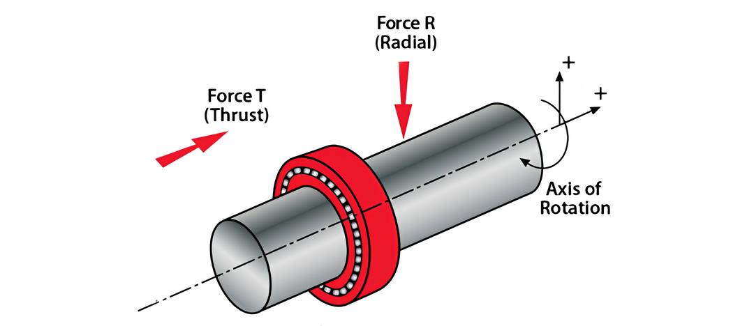
Figure.1 - Machines can use fully rotating joints
This is not the case when we look at flight developed by animals. Due to the constraints of biology, their limbs must be connected to the rest of their organism. Therefore, they cannot make use of rotary joints that complete a full revolution. This constraint has meant that flying animals have developed locomotion that depends on oscillating joints, rather than rotary joints, as in the case with manned aircraft. Animals must therefore oscillate their wings back and forth to achieve powered flight.
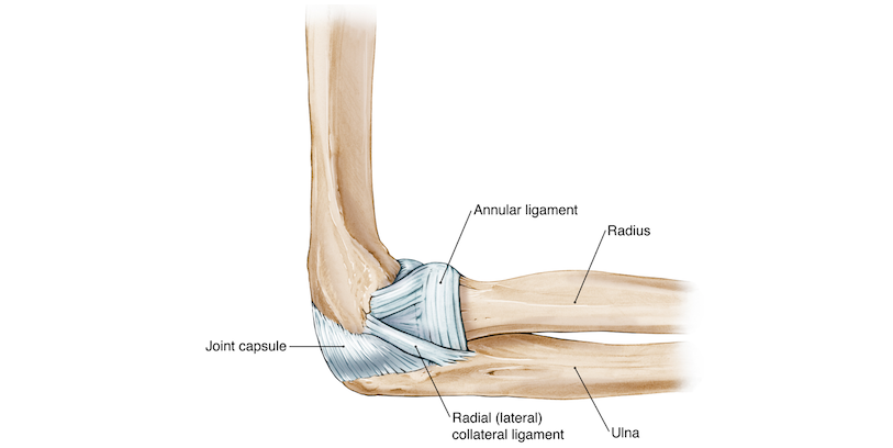
Figure.2 - The rotary joints of animals cannot complete a revolution
If we pay close attention to the flight of different animals, we can notice significant differences in the way in which they move. For example, birds tend to move horizontally from place to place, while insects like bees or mosquitoes tend to fly stationary for prolonged lengths of time.
Video.1 - Bird in horizontal flight
In one case, flight is dominated by high-speed level motion, on the other, it is dominated by rapid motion of the wings with very little motion of the body. This is directly analogous to airplane flight and helicopter flight respectively.
Video.2 - Insect at hover
Despite the differences between the two modes of flight, animals have the common property of using flapping wings. This means that unlike man-made solutions that achieve particular flight profile, animals have managed to use a similar over-all design in different situations. This flexibility in flapping winged flight makes it appealing from the perspective of designing an aircraft, as it can uniquely achieve a transition between level and hovering flight with the same platform.
See: Vertical takeoff and landing aircraft - Combining airplanes and helicopters
There are also theoretical arguments that make flapping flight appealing. One of them is that a flapping wing covers a larger area as it moves compared to a propeller. According to actuator disk theory, whenever a propeller (or in this case a flapping wing) accelerates air over a larger area the power required to generate a particular thrust is decreased. This leads to greater propulsive efficiency in the case of an airplane, and lower power requirements in the case of a helicopter. These observations make flapping flight an appealing area of study because it differs significantly from other more well-researched methods of flight. The term used to refer to aircraft that fly by flapping their wings is an Ornithopter.
Initial aircraft design
We can attempt to build an ornithopter and therefore replicate the flight of animals by using servo-motors. These are relatively inexpensive devices composed of a motor with a feedback loop that allows it to control its angular position. By commanding a servo motor to undergo an oscillation and then connecting the servo motor to an appropriate joint, it’s possible to replicate the articulation and motion of animal wings with a simple and inexpensive device. We can further relax the requirements of the ornithopter by focusing only on horizontal flight (analogous to bird flight), rather than trying to achieve the high-powered hovering flight of insects.
Therefore, this project concerns itself with developing a radio-controlled ornithopter powered and controlled by two servos. Each servo is connected to a wing and flapped independently. This allows the motion of the wings to be controlled through software rather than through a specially designed mechanism. There are many advantages to this approach, mainly that it is very easy to adjust the amplitude of the flapping motion, and the wings may be oscillated asymmetrically to achieve directional control.
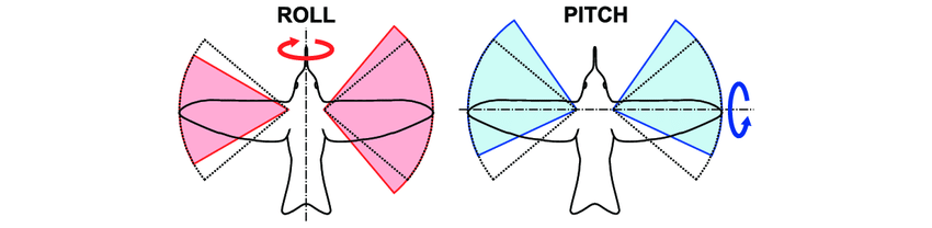
Figure.3 - Wing trajectory modifications as control actions
Through the use of servos, it’s also possible to change the waveform that’s used to drive the wings. That means that if a particular waveform is better suited for a certain flight condition, this modification can be made on the fly rather than requiring complex mechanical changes to an existing design.
Aircraft Iterations
Iteration 1:
The first version was a test platform to observe how effectively servos could oscillate a long spar. It also served to test springs connected to the servos in series or parallel. These springs can reduce the power drawn by an oscillating mass driven by a motor if tuned correctly. For this design a coil spring was connected in series with the servo and a leaf spring was used for a parallel connection.
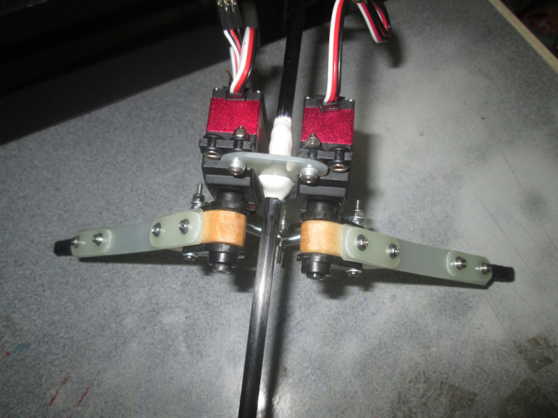
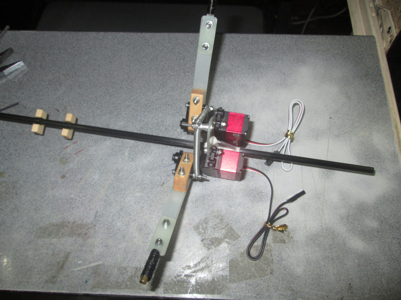
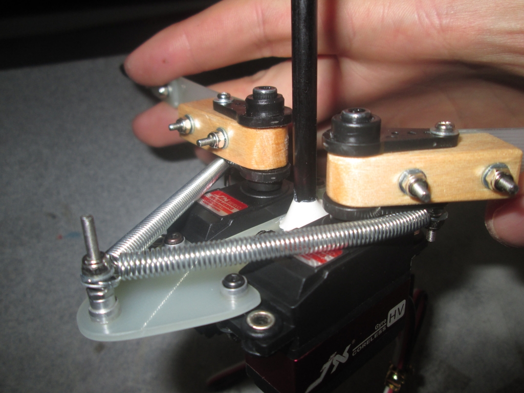
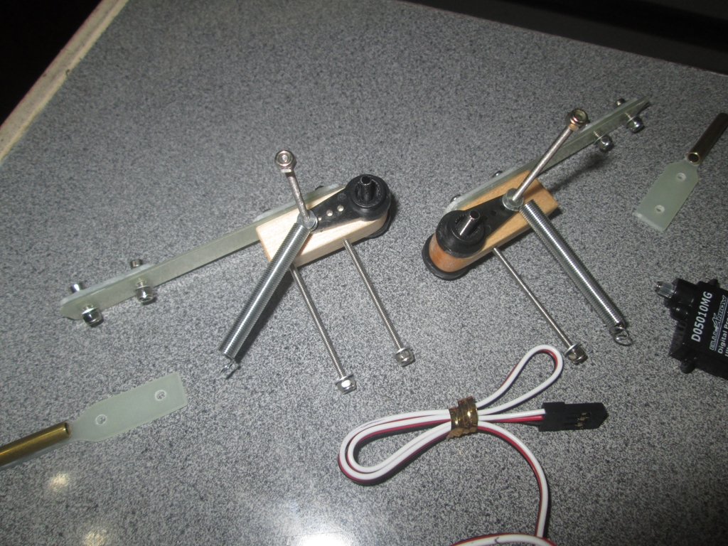
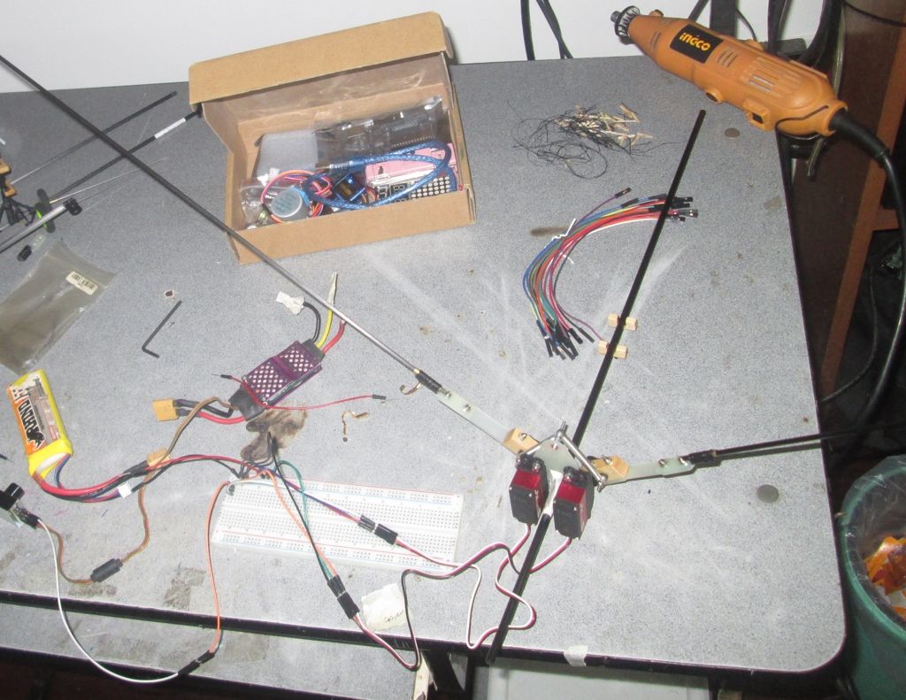
Figure.4 - The inital version had awkwardly mounted springs
Iteration 2:
The second iteration was a complete aircraft. The design employed a pair of skewed hinges to hopefully achieve roll and pitch control. Unfortunately, test flights revealed this system did not work and barely redirected the aircraft. In addition to this, the servos were undersized and were under too much load. This resulted in the servos getting very hot to apply the desired torque. The wings were also inefficient and could not generate the required thrust for the aircraft to sustain flight.
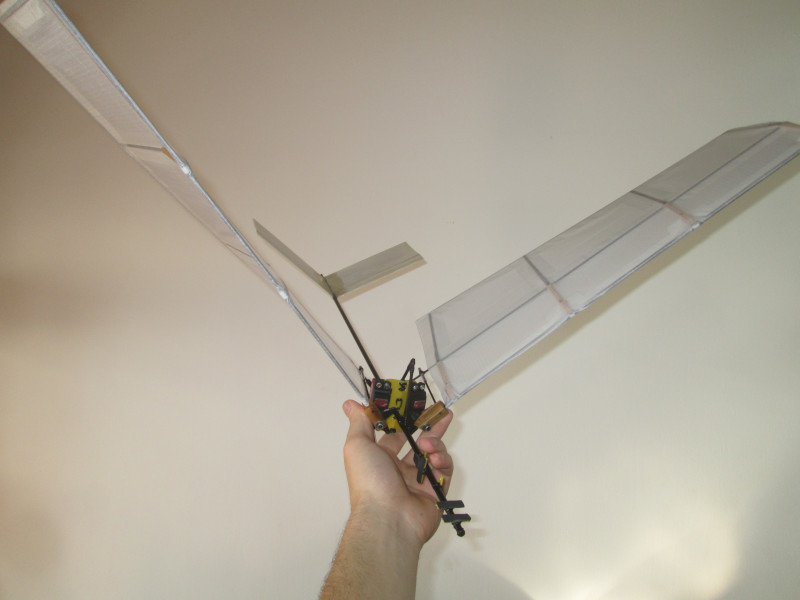
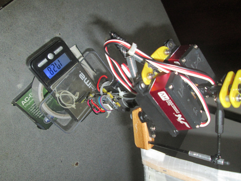
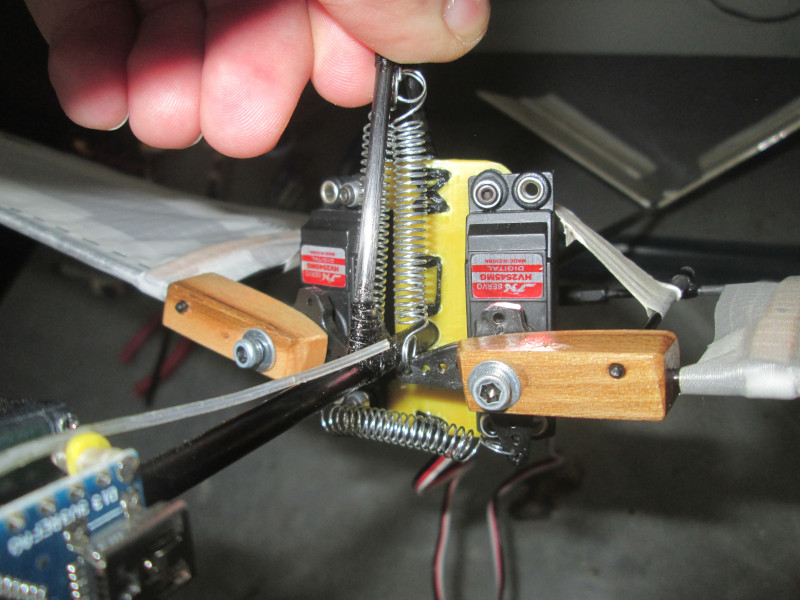
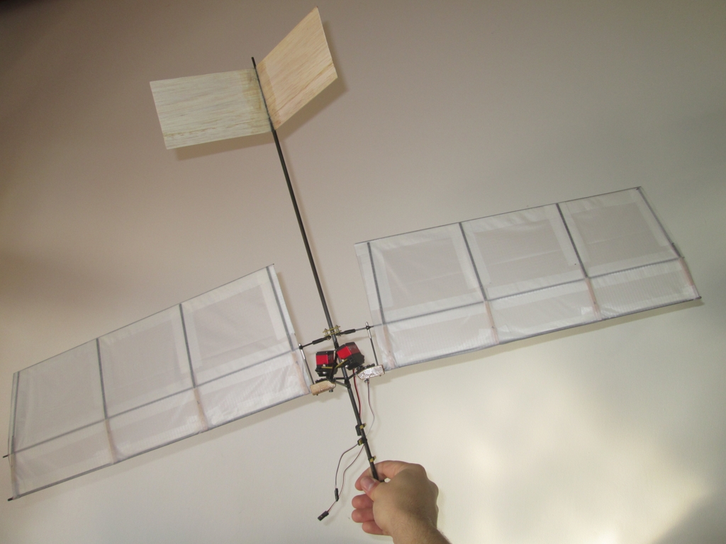
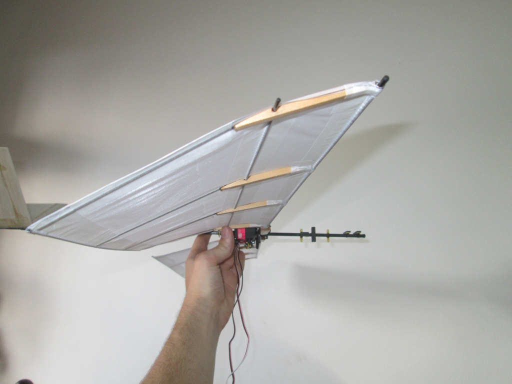
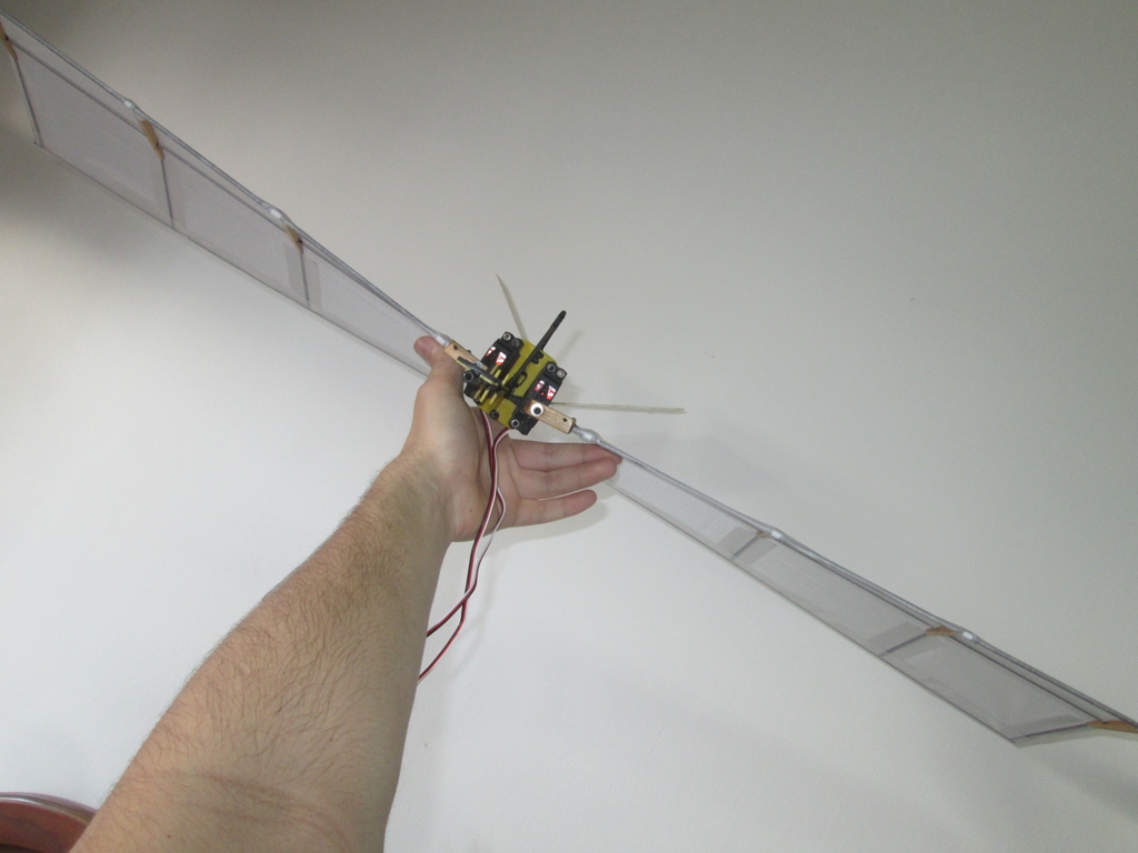
Figure.5 - The first iteration was built with little concern of the wing design
Video.3 - Underpowered servos
Iteration 3:
The third iteration built upon the second version. Control was accomplished separately through a controllable tail, and larger servos with four times the torque were used to reduce the likelihood of excess torque. To complement this, the servos were connected indirectly to the wings via a lever arm to double the torque applied to the wings.
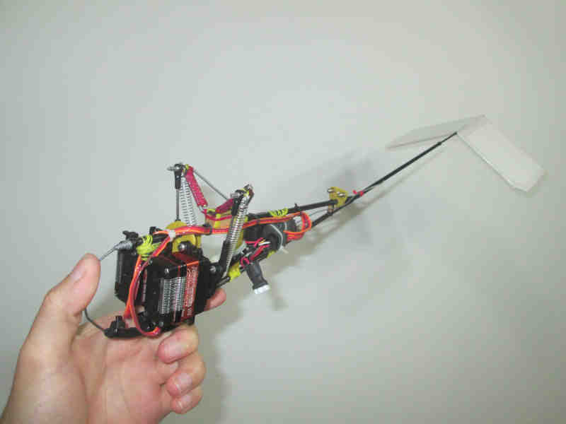
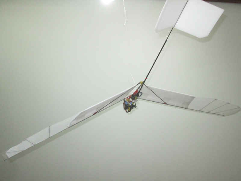
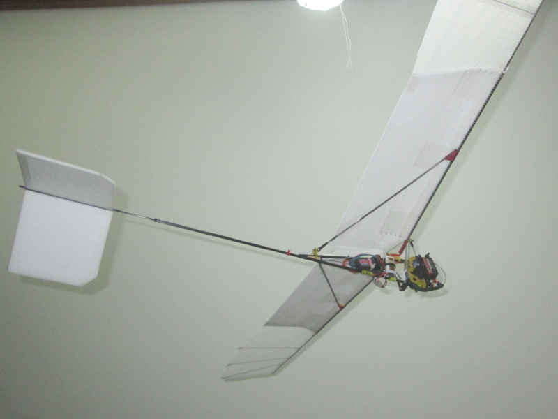
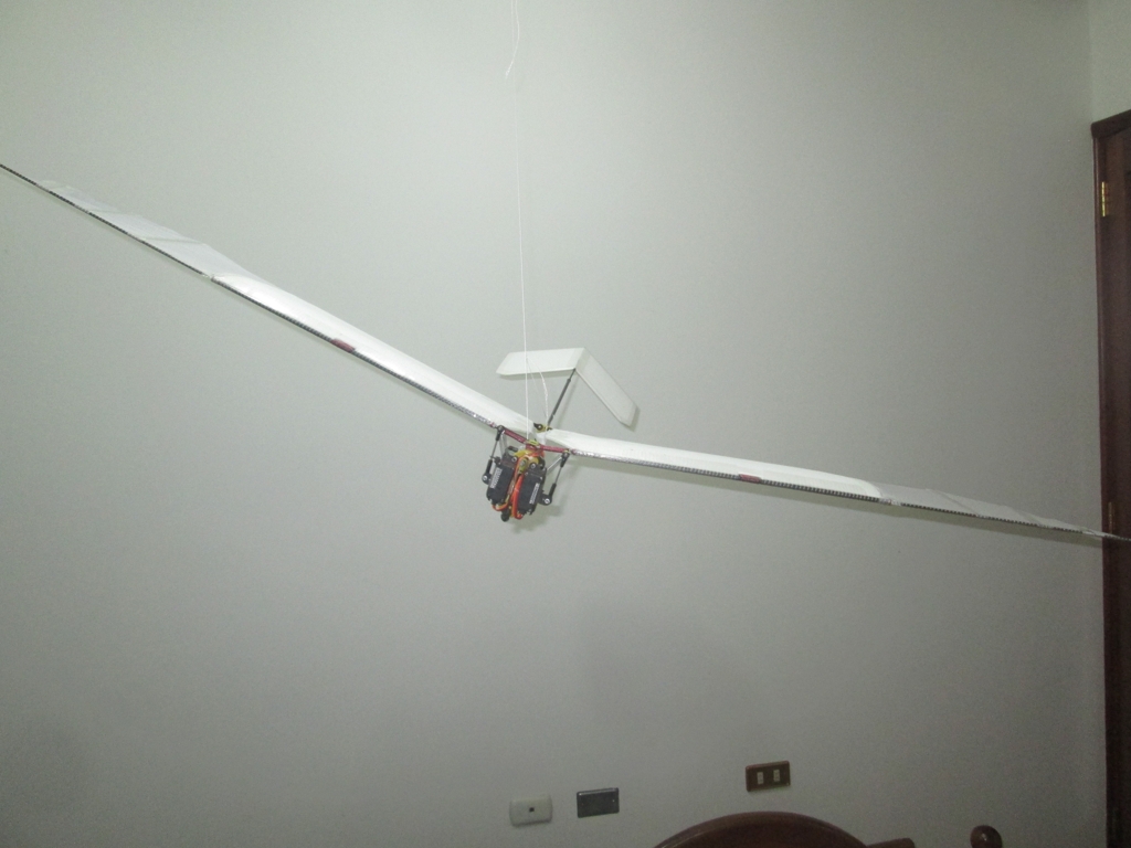
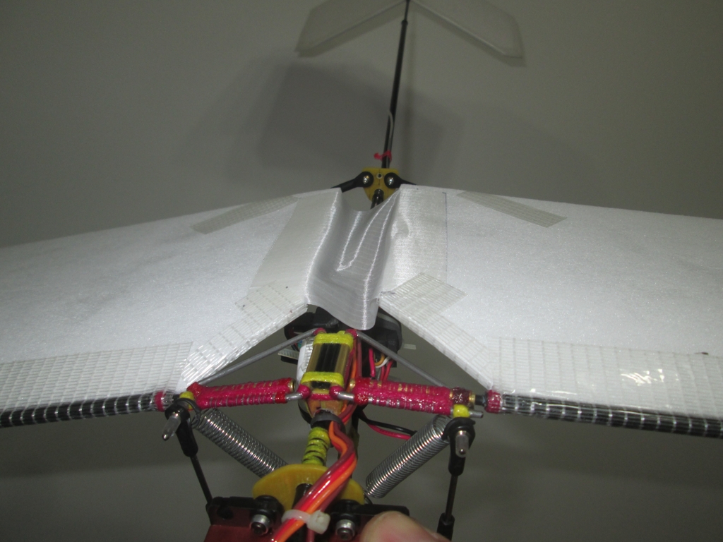
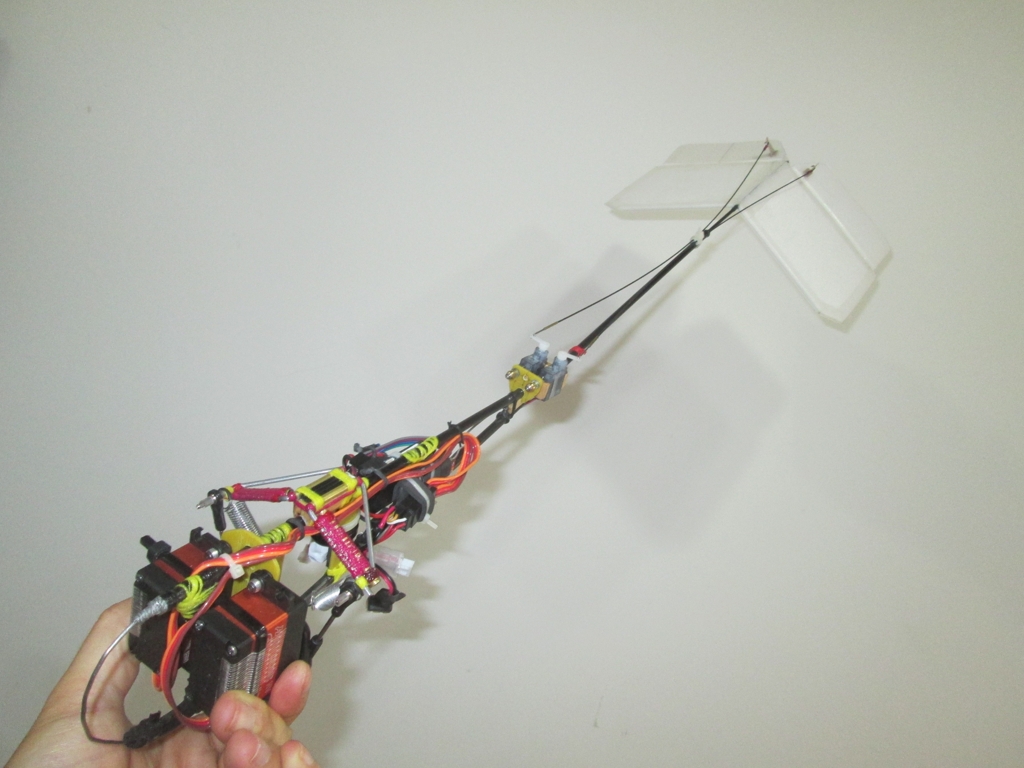
Figure.6 - The second version of the ornithopter was much more refined
While this overcame the issues of driving the wings, the wing design was lacking. The first iterations of the aircraft were incapable of maintaining powered flight. They were capable of achieving gliding flight but powered flight was underwhelming at best. To some extent, it seemed like flapping the wing hurt the ability of the aircraft to stay aloft. The glide path while flapping the wings was actually slightly worse than when the wings were kept straight and the aircraft allowed to glide. Evidently the propulsion system was not working as it did not propel the aircraft.
Video.4 - Inefficient wings
To overcome this problem, I experimented with increasing wingspan and modifying the elasticity of the wingtips. These modifications had a two-fold effect. For one, the longer wing tips would allow the propulsive section of the wing (the tips) to produce more thrust as they moved faster through the air. Secondly, the elasticity was adjusted such that the wings would easily twist and unload when flapping upwards, but were much harder to twist when flapping downwards when they needed to provide lift and thrust simultaneously. These modifications had a significant impact on the propulsive efficiency of the aircraft, as it could now maintain a much shallower glide as compared to when the wings did not flap. This indicated that the propulsion system actually worked and aided the ability of the aircraft to stay aloft. Despite these gains, the aircraft still did maintain level flight.
Video.5 - Assymetric wing elasticity
The next solution was to increase the power of the servos that drove the wings. This required that the original servos be swapped for more powerful brushless servos with motors capable of outputting more power. When coupled with a more powerful battery that raised the voltage 11.1 volts (3 Cell lipo) from the original 7.2 volts (2 Cell Lipo), the aircraft was finally able to barely maintain altitude, albeit with ideal wind conditions.
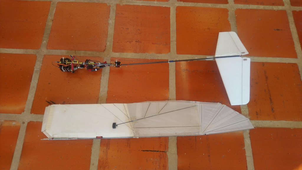
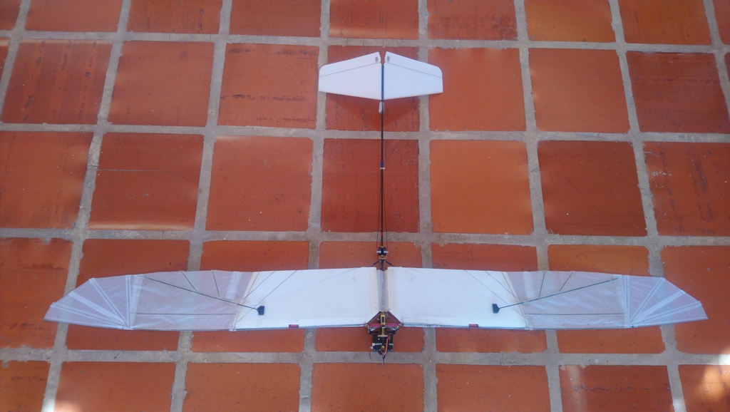
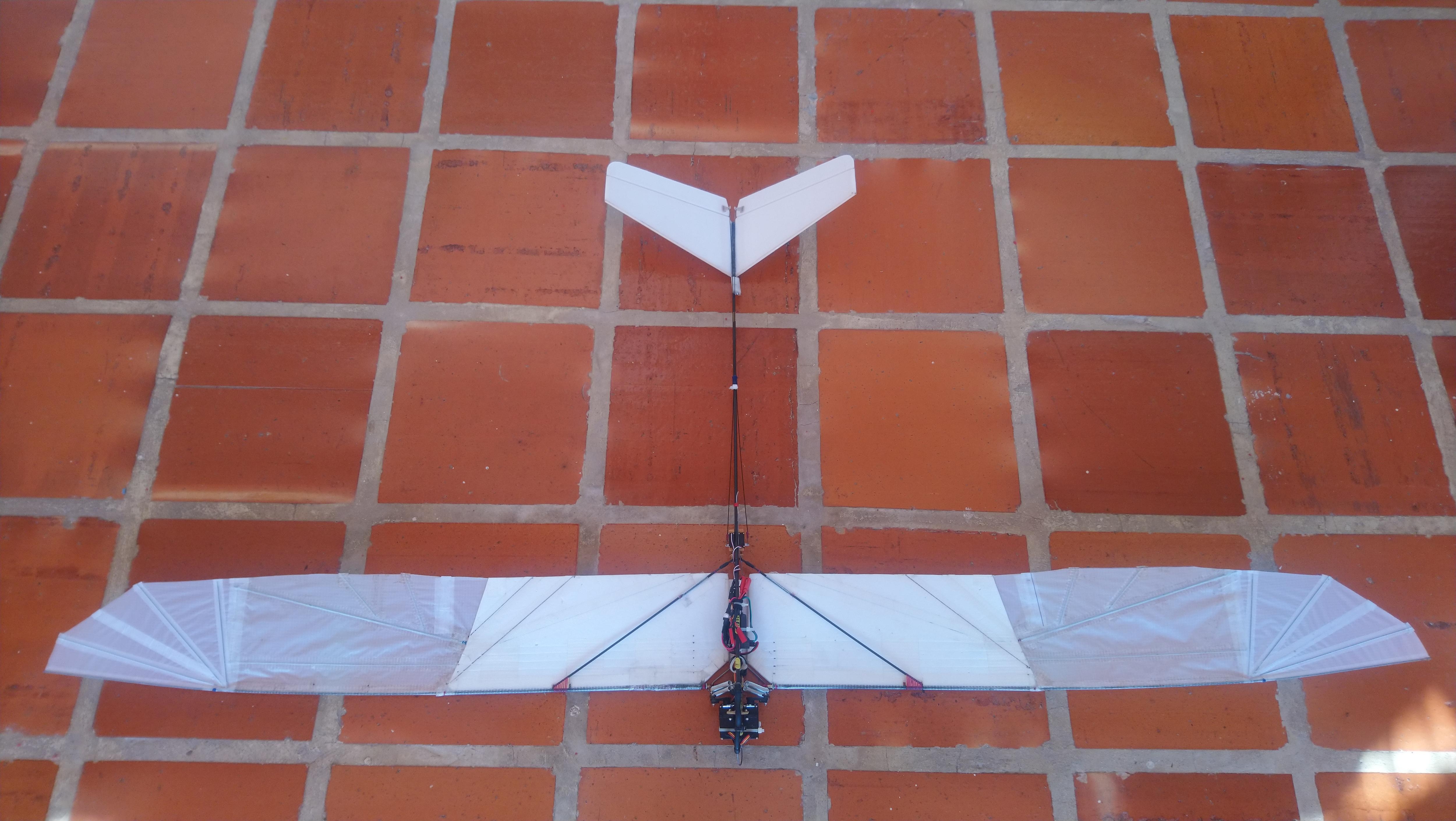
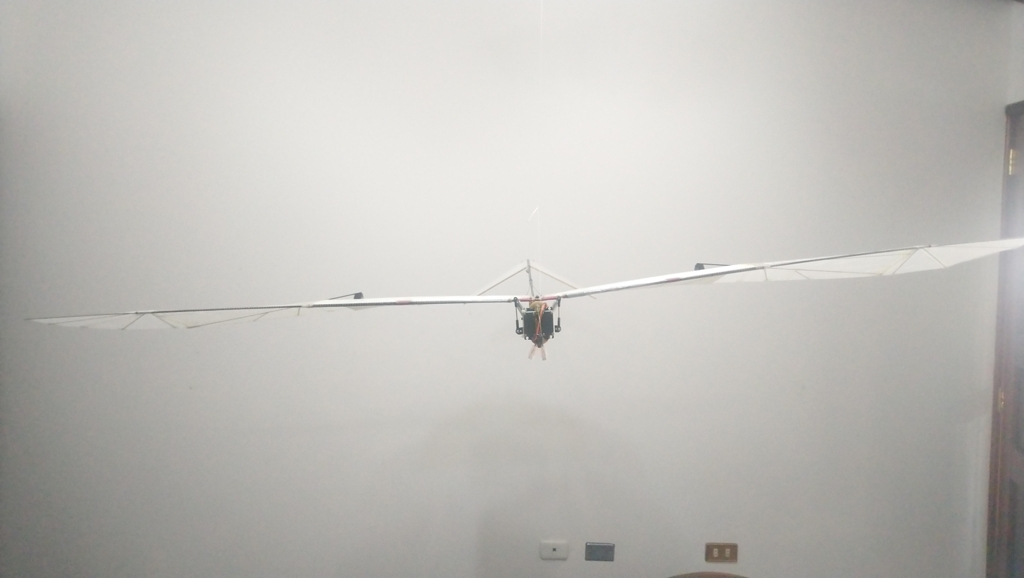
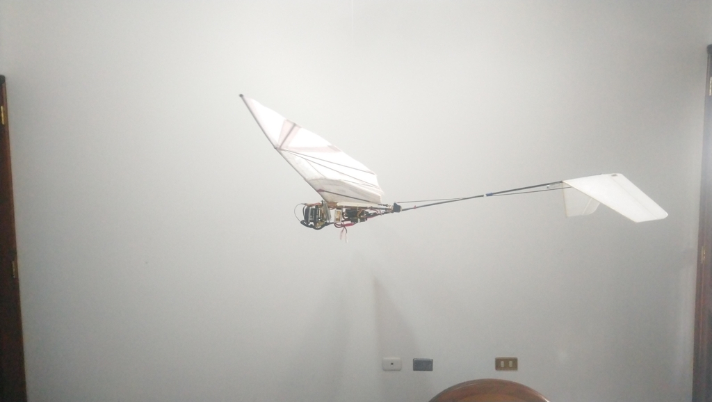
Figure.7 - The wings and tail were made larger to increase the wing area
Video.6 - First succesful powered flight
Unfortunately, the extended wings had the consequence of reducing the torsional elasticity of the wings so that the wing tips would come very close to fluttering when the aircraft was in level flight. To alleviate this problem, the wings were doped with a polyurethane coating to make them more rigid and waterproof. Moreover, a small piece of lead was installed at the tips to move their center of mass forward of the local aerocenter. While these changes helped suppress flutter, they unfortunately increased the moment of inertia of the wings such that they became harder to accelerate. The greater inertia meant a significant portion of the available power was being wasted beating the wings back and forth. This greatly hindered the ability for the servos to flap the wings and the aircraft was no longer capable of maintaining altitude.
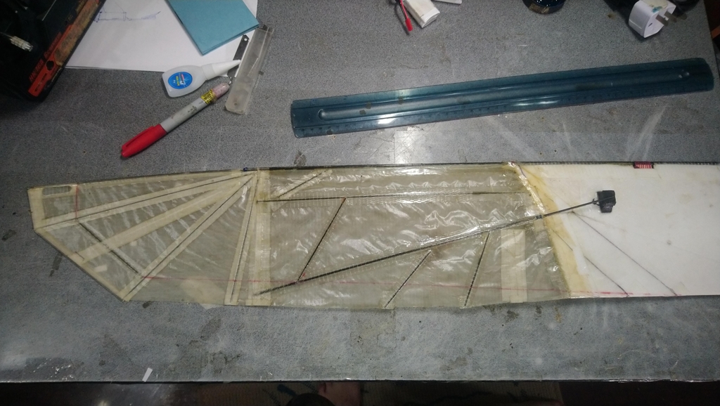
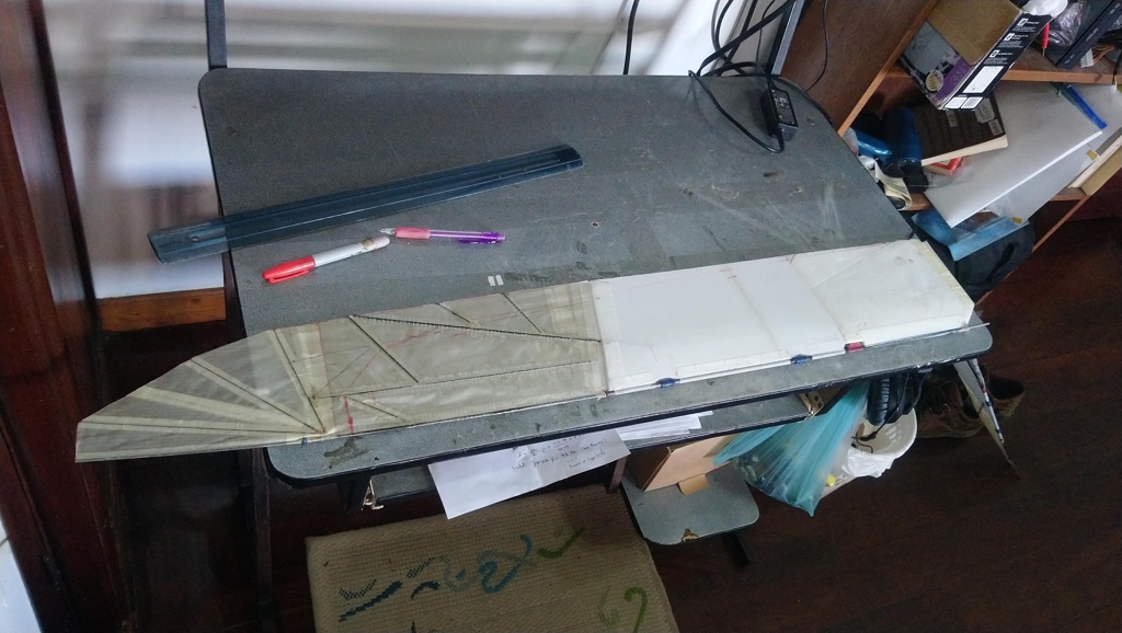
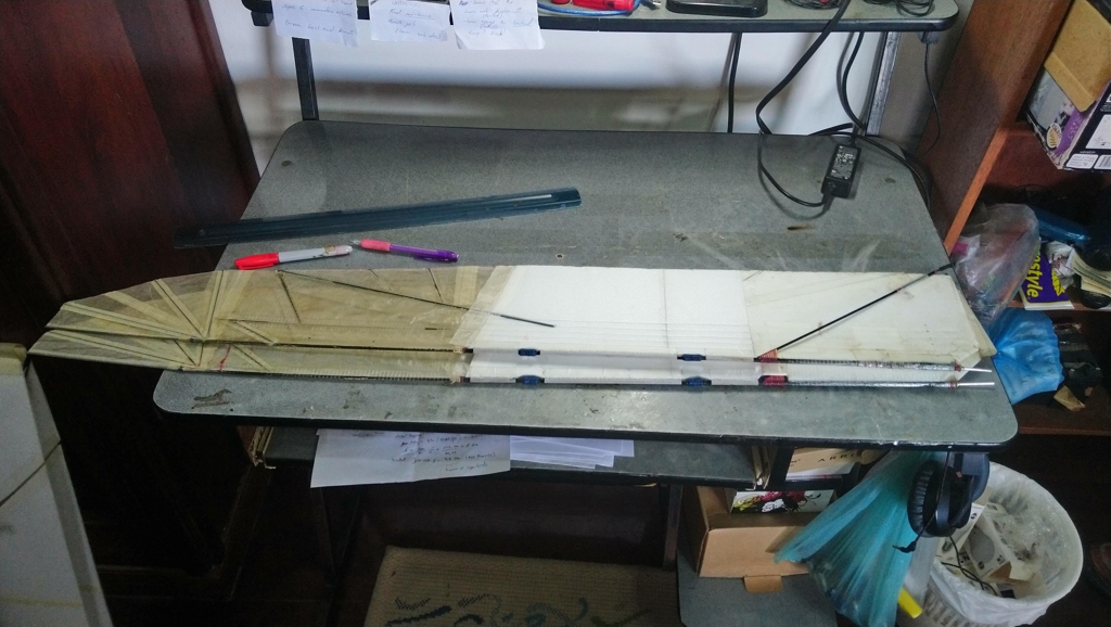
Figure.8 - Heavier wings massively decreased performance
Video.7 - Heavy extended wings
To backtrack from this mistake, the tip weights were removed and the wingtips were slightly shortened to decrease the moment of inertia. Moreover, it was deemed that broad wingtips were not as beneficial as longer wingtips, as broader wingtips generated more induced drag. Therefore, area was removed from the trailing edge of the tips as it added mass and did not have much aerodynamic impact. To further improve the likelihood of powered flight, the voltage of the servos increased to approximately 18.5 volts (5S Lipo). This increase in available power, coupled with the modified wings, had a tremendous effect in the ability of the aircraft to maintain altitude. During a test flight, the aircraft was capable of maintaining height and climbing somewhat aggressively. This led to a long, prolonged flight where the aircraft was eventually landed for fear of overstressing the servos as they had been operating continuously for many minutes.
Video.8 - Excellent prolonged flight and climb
Since adding more power greatly benefited the ability of the aircraft to fly, voltage was further increased to approximately 22.2 volts (6S Lipo). Unfortunately, this did not last very long as the stresses of the higher power output quickly broke one of the wings. Therefore, it was deemed that this level of power was too high for the machine to safely absorb it. It was also observed that the flight performance began to decay even at the higher voltage. This was likely due to the servos drawing significantly more power than before, and the batteries were too old and incapable of maintaining the required power.
Video.9 - Flight performance began to decay shortly afterwords. A sign of bad batteries
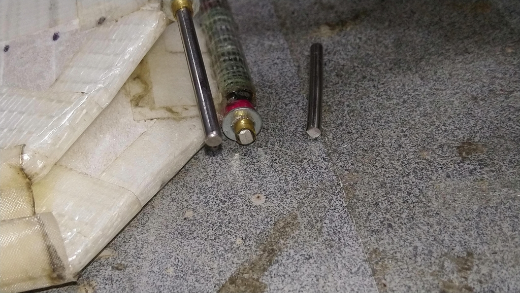
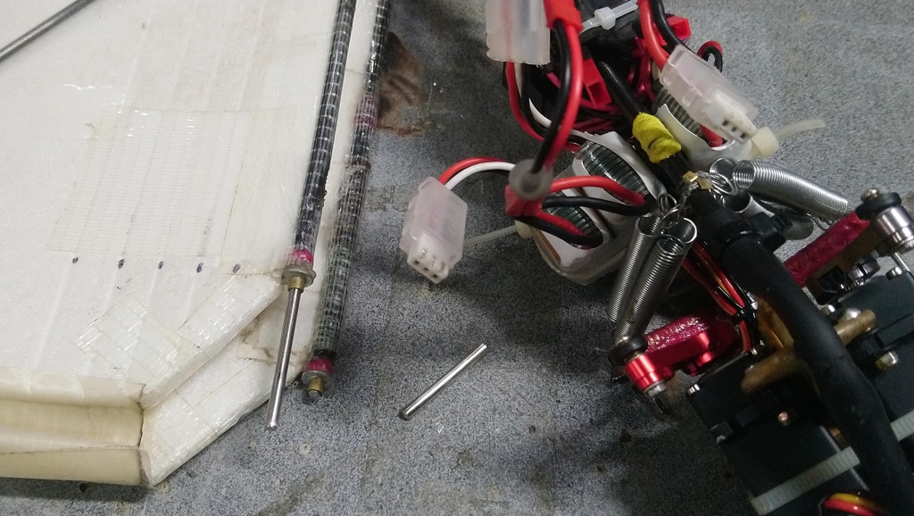
Figure.9 - The steel roots of the wings broke due to the huge loads
Conclusion
Despite the challenge that flapping flight presented, it was ultimately possible to make an ornithopter that flew that was completely powered by servo motors. This was a great personal success, but the challenge involved in achieving this victory makes an ornithopter somewhat unappealing. This is because servos are not efficient when oscillated back and forth, and while they are capable of outputting a degree of mechanical power, they do so at a much lower efficiency when compared to a motor that rotates continuously. Therefore, one is exchanging the ease of control for much higher power requirement when using servos. It also became evident this method of flight is less efficient than a rotary winged or propeller-driven aircraft. This is because the constant acceleration of the wings creates a power loss that is not existent in devices that have rotating joints. This inertial loss means that an ornithopter draws more power than an equivalent airplane with a propeller. When combined the inefficiency of oscillating servos, we end up with a system that consumes a great deal of power but has underwhelming performance. We can interpret this as a propulsive efficiency that is depedant on the inertia of the wings.
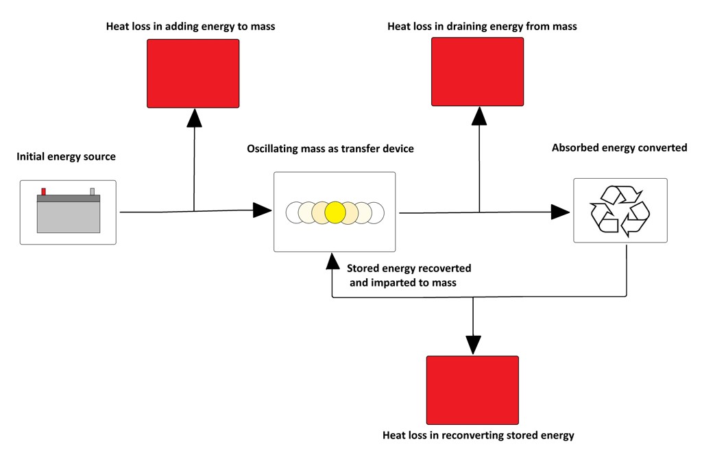
Figure.10 - The conversion between kinetic and potential energy causes energy loss
This is not to say that ornithopters cannot be efficient, but their wings need to be designed with great care such that they possess a small moment of inertia. Otherwise, the inertial loss associated with their mass will make them uncompetitive compared to other platforms. We can clearly see this constraint in the wings of birds and insects because their structures are very light and sparse. They only possess the minimum amount of material needed to provide a rigid enough structure for the loads the experienced in flight. But beyond that their mass is kept to an absolute minimum. We can take inspiration from this fact to design better ornithopter wings. Their mass is a critical component in the design process and must be factored in to make an efficient device. This leads us to the unusual compromise where both the mass of the wing and its aerodynamic properties must be optimized, one in detriment of the other, to obtain an ideal system. This is very different from, say, an airplane where the aerodynamics are of primary concern and the mechanical properties are subject to these requirements.
Arduino Code
The program to control the ornithopter is designed to receive 3 PWM inputs from an RC receiver operating in MODE 2 and output 2 PWM signals for off-the-shelf hobby servos. The aileron (1) and elevator (2) channels are used to bias the dihedral angle of each wing, with the aileron rotating the wings in unison while the elevator changes the dihedral angle. The throttle channel (3) changes the amplitude of a fixed-frequency oscillation. The controller also is equipped with a low-voltage cutoff routine. This will disable the throttle channel to prevent over-discharging a battery. See the attached schematic for an example of the required circuit:
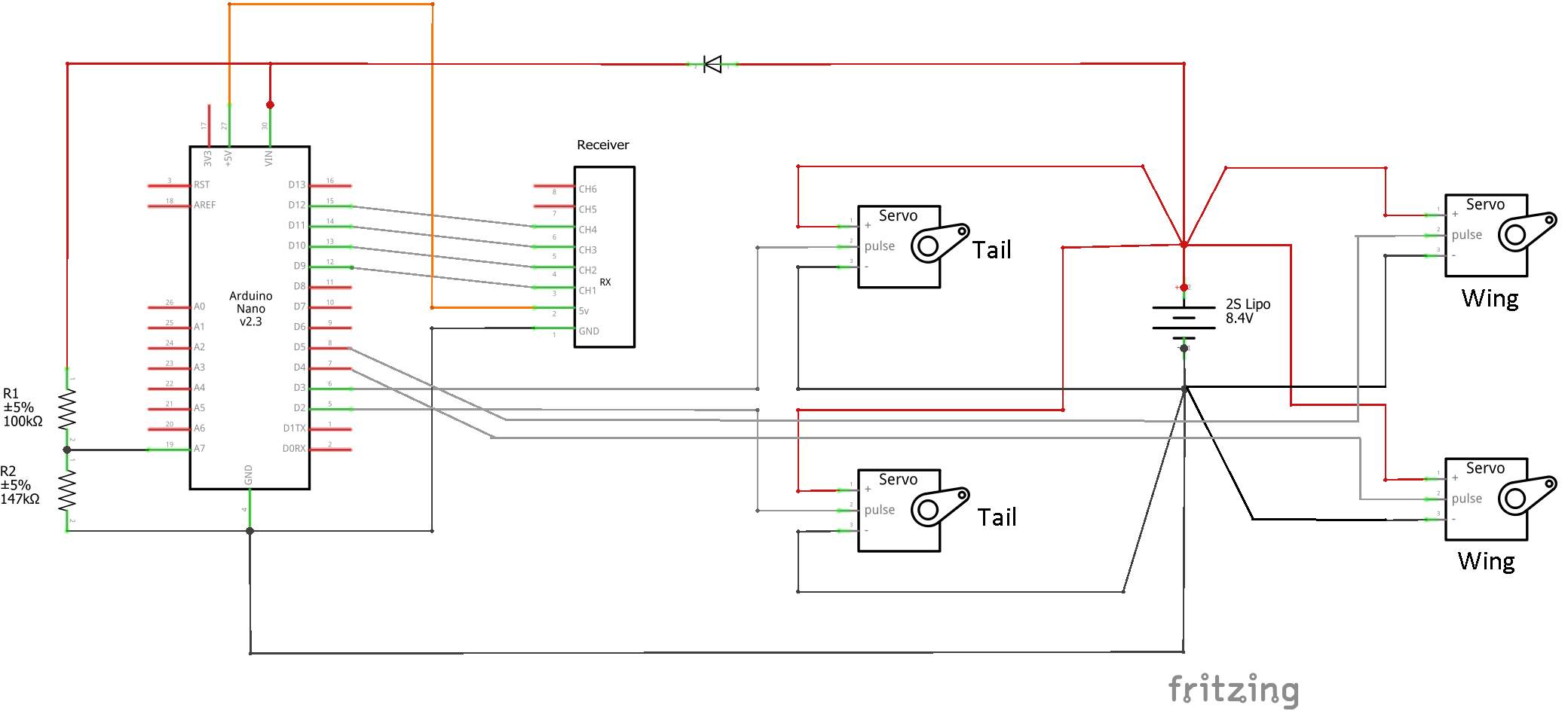
Figure.11 - Schematic for servo controller
The operation of the servo controller can be seen in the following video:
Video.10 - Demonstration of servo controller
Github Repo: ServoFlappingControl