Line following robot with a PID controller
When I was an undergraduate, I took a lab course in electronics where the final project involved building a line-following robot. This small wheeled vehicle needed to navigate a circuit without any external assistance, following a line until it reached the end or continued around a closed loop. Such projects are common when first learning about Arduinos as they provide a platform to explore not only electronics but also programming and closed-loop control. Here’s a great example of a fast line-following robot:
This small vehicle can follow an arbitrary line placed on a surface.
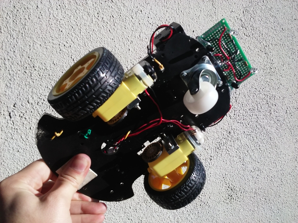
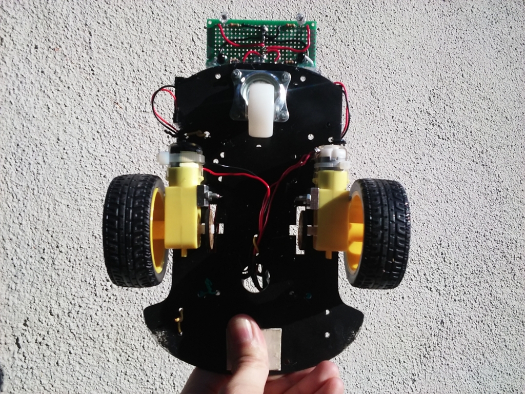
At the time, a machine like the one above represented the kind of performance we could potentially achievable. Although the course provided the necessary equipment, we couldn’t replicate the high-speed motion seen in the example due to limitations in the hardware that was available. However, we could still achieve a similar capability for accurately following an arbitrary circuit. The logic for guiding the robot could be executed through an Arduino Nano, so it would allow us to implement various control algorithms. Mechanically, the robot consisted of a standard off-the-shelf chassis featuring an acrylic frame with two geared DC motors and a third, uncontrolled caster wheel at the front:
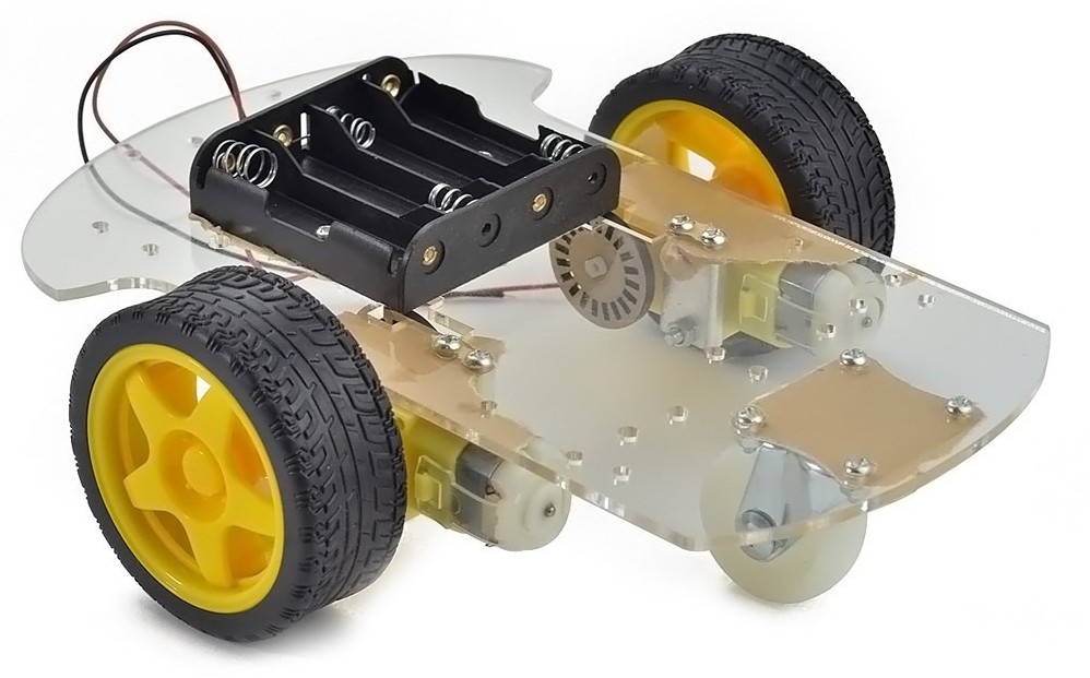
The freely moving wheel allowed for easy control through differential wheel velocity, similar to how a tank or tractor operates. By rotating both wheels at the same velocity, the vehicle could move forward, while any speed difference would cause it to turn. This configuration enabled full control of the vehicle’s velocity and orientation without significant mechanical complexity, allowing us to focus on developing the control algorithm. At the core of this system were a pair of infrared distance sensors:
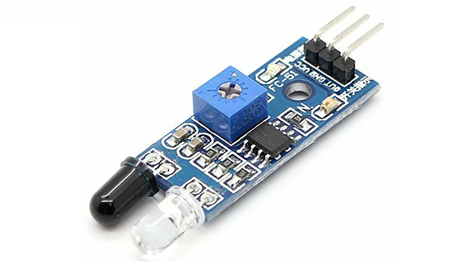
Sensor module based on an infrared LED and a photodiode.
These devices measured the reflection of a surface illuminated by an infrared light source. Since dark surfaces reflect less light than white ones, the sensors could detect a dark object in front of them. We could then measure the displacement of a dark line between them by using two sensors in close proximity. This is because as the line passed beneath a sensor, it progressively decreased the reflected light until it was completely blocked. This proportional response allowed us to create a function mapping the sensor outputs to the lateral displacement of the robot relative to the dark line.
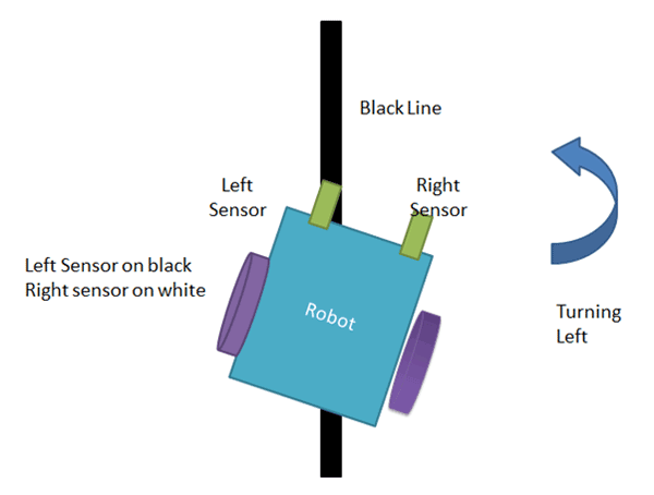
See: Line Follower Robot using Arduino by Circuit Digest's Saddam.
With the sensor providing a continuous value representing the position error, we employed a PID controller to adjust the robot’s target rotation. This signal was fed to an H-bridge module, which connected directly to the motors and supplied the power needed to drive them. However, precisely controlling motor velocity posed challenges due to significant stiction and cogging torque in the mounted motors. This meant they wouldn’t rotate unless a minimum torque was applied to their rotors (the internal magnets connected to the output shaft). It was only once the motors began to move and a minimum speed was reached that motor velocity correlated directly with the applied voltage until. Thus, a corrective algorithm needed to be implemented in this slow-speed, non-linear behavior region, to accomplish fine velocity control.
To address this problem, we controlled the motor speed using pulse frequency modulation. Each pulse of the waveform was long enough to dislodge the rotor and cause it to rotate slightly into a different “tooth” generated by cogging torque. As a result, the motors moved similarly to stepper motors that have discrete jumps in rotation. By increasing the pulse frequency of the waveform we could cause the motors to rotate faster. At some empirically determined frequency, we made the algorithm switch to pulse-width modulation as the rotor gained enough inertia to continue rotating smoothly and PWM enhanced this motion.
An example of a motor with cogging and one without.
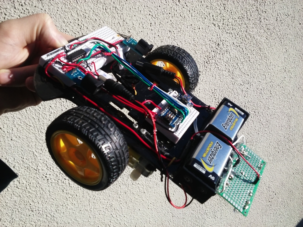
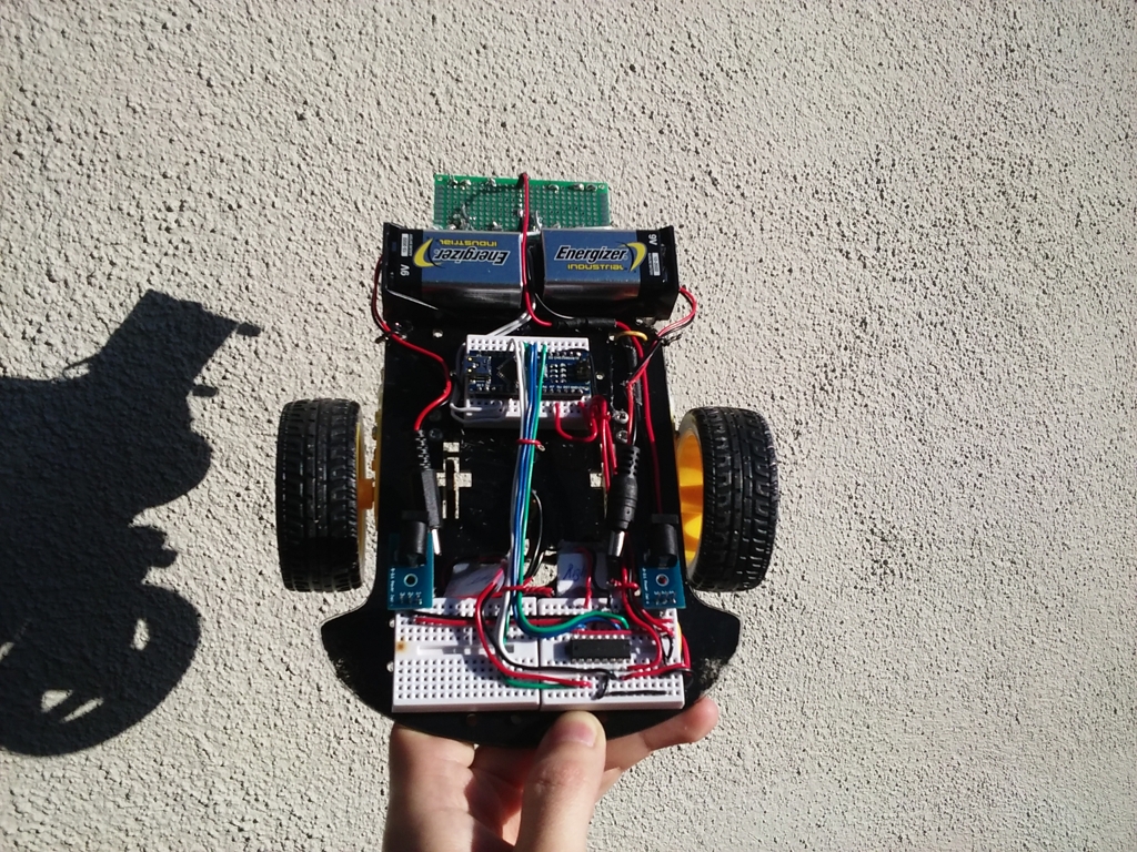
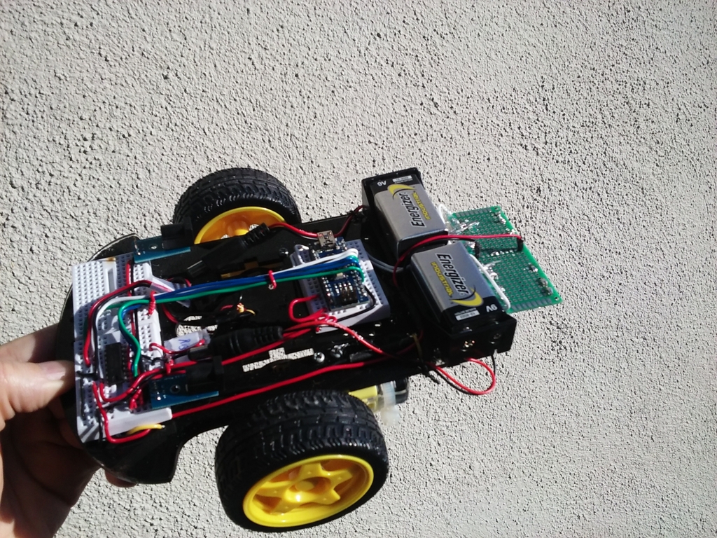
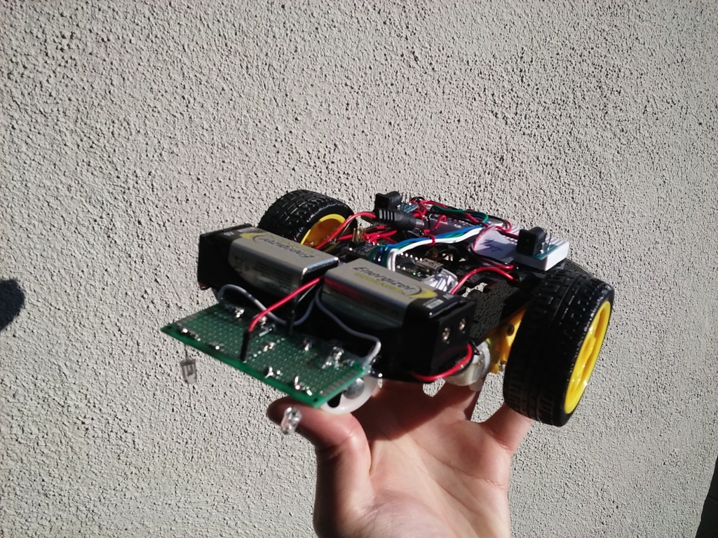
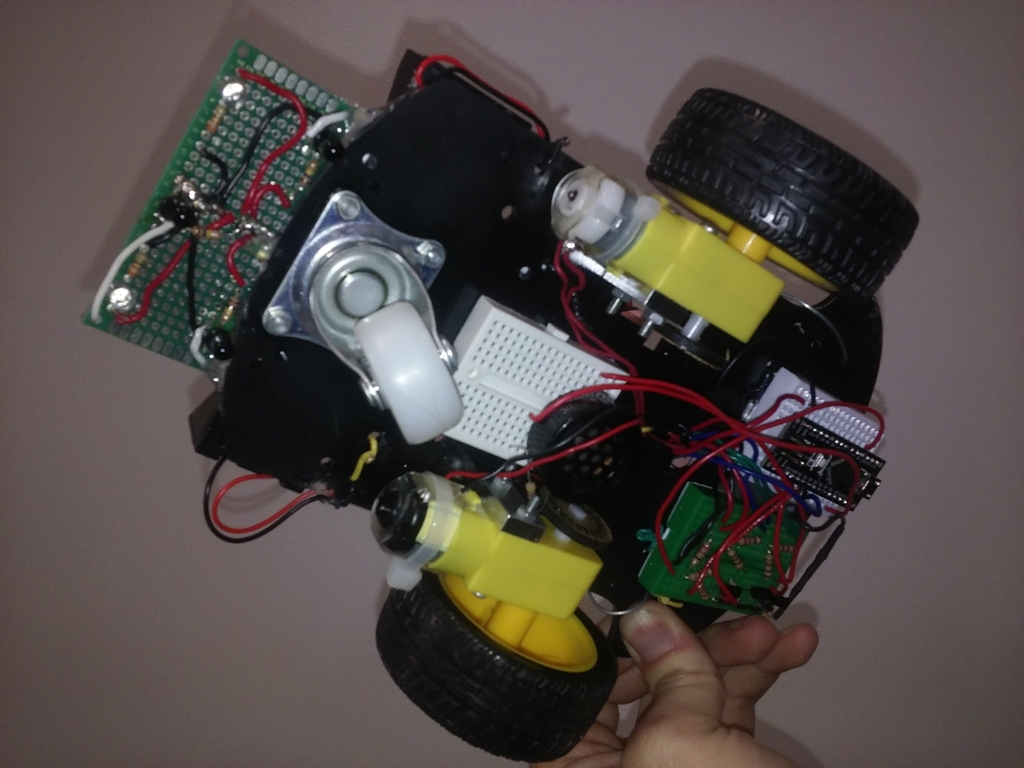
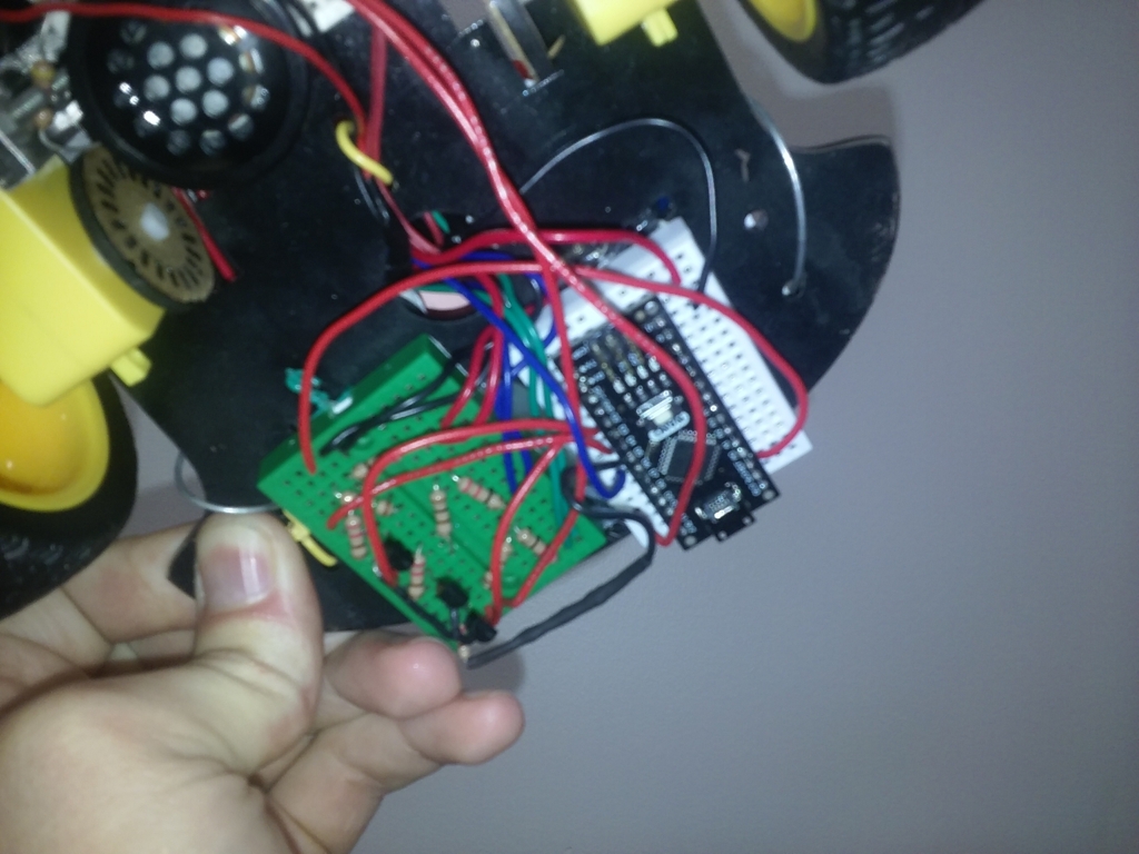
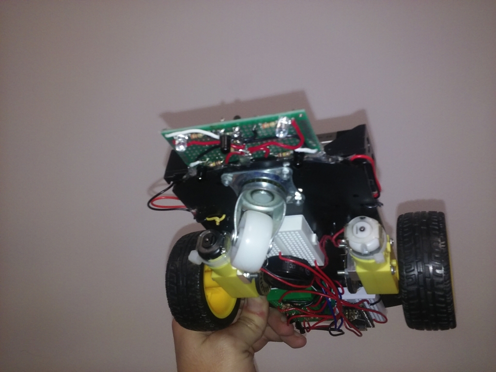
With the control algorithm foundations established, we assembled the robot using breadboards and hook-up wires (See: Guide to Breadboard Wires by Ankit Negi). The end result was a neat and compact circuit that could be modified quickly.
The assembled robot made extensive use of hook-up wires.
The vehicle was only equipped with the infrared sensor array so its output was the sole variable determining the robot’s behavior. The schematic of the robot’s electronics illustrates this:

The control circuit consisted of an Arduino, the sensor array, and two motors.
To enhance the robot’s ability to follow an arbitrary path, the control algorithm was made to reeduce the speed of the robot when it detected a large displacement from the sensor array. This adjustment allowed the robot to have enough time to rotate and continue tracking the line. While this solution doesn’t guarantee the line is tracked under all conditions, it significantly improves functionality for most paths. The following video demonstrates the completed robot’s operation:
Operation of the completed line-following robot.
As shown, the robot performed well once the PID controller coefficients were correctly adjusted. However, this tuning was surprisingly challenging as the sensor array functioned accurately only over a narrow range of displacements above the line. Beyond this range, measurements became unreliable and the PID controller would fail to function properly. The difficulty in tuning stemmed from this limited band of stability that had to be maximally exploited. When the robot was stationary, this issue was manageable provided the line didn’t move beneath it too quickly. However, once the vehicle began moving forward the rotational response had to be swift to maintain the line tracking. Consequently, it was better to keep the PID controller underdamped allowing it to track rapid movements more effectively than a critically damped system.

For a detailed discussion of the control algorithm used in the robot, along with necessary signal processing and corrections applied to the sensor inputs, see the report submitted at the end of the course:
PDF: Line Following Robot - Detailed Discussion of Circuit and Control Algorithm
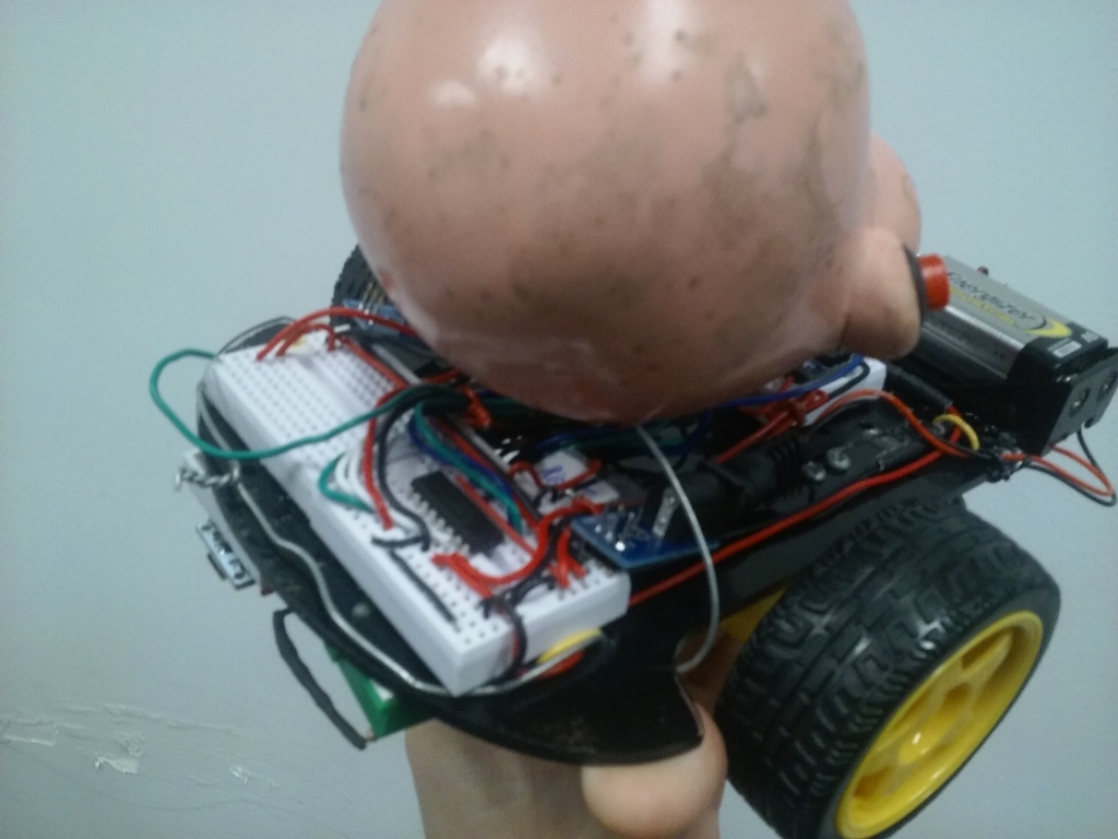
Since this was a group project, we equipped the robot with an additional Arduino connected to a speaker. Although it played no role in guiding the vehicle, it was a fun element to add at the end the project. We attached a doll head to the robot and made the speaker emit quirky sounds as it ran around the circuit. It was weird but it was definitely entertaining!
The final "doll-head" version of the robot. Beware, it screams!
GitHub Repository
The code for the robot can be found at the following repository: LineFollowingRobot
