SB-1 | Self balancing robot stabilized with a gyroscope
While learning how to program Arduinos, I frequently encountered different versions of the self-balancing robot. This robot is essentially a two-wheeled platform that is unstable in one direction and needs to be stabilized to maintain the balance of an inverted pendulum. To keep the vehicle upright, the wheels are rotated to generate horizontal accelerations that prevent the body from tilting forward. As a result, the vehicle remains upright by actively applying torque to the wheels. This project is a great example of an unstable system being forced towards a stable condition through a controlled feedback loop. It’s also an excellent way to learn about control algorithms and their strengths and drawbacks.
A great example of a self-balancing robot by: RZTronics
This project felt like an ideal learning opportunity. Most designs for these robots use stepper motors or DC motors with rotary encoders to measure their position. Both approaches allow for precise control of the wheel’s angular velocity since their position can be accurately monitored. In the case of stepper motors, if they are rotated slowly and under a light torque load, they can achieve precise motion control without directly measuring their position. This is because they rotate in discrete, known steps. By counting the steps commanded to the motors, the position can be automatically determined.
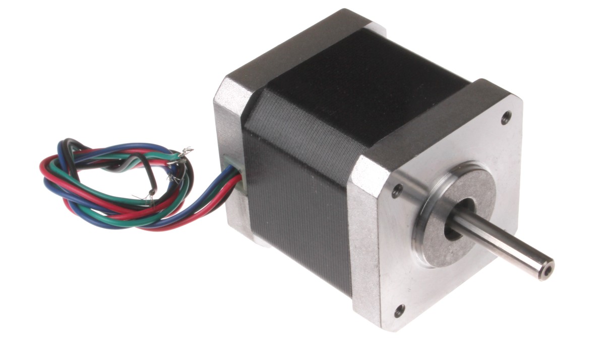
A direct-drive stepper motor is designed for low-speed, high-torque operation.
On the other hand, DC motors do not rotate through a known angle, requiring a measurement system to sense their position. In this case, a rotary encoder can be used to count the number of steps and determine the angular rotation of the DC motor. This angular position can then be used as the basis for a PID controller, which applies the necessary voltage to the motor to achieve a target angular position. Although this method is more complex than using stepper motors, it has the advantage of applying larger torques at higher speeds with lower energy consumption.
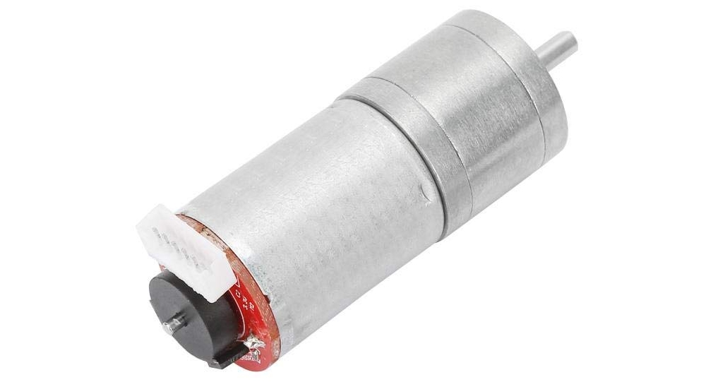
A DC motor needs to be geared to apply torques similar to a comparable stepper motor.
Given the advantages of DC motors, they are naturally appealing for a wheeled robot. However, using rotary encoders adds complexity and cost compared to stepper motors. As a challenge, I decided to use DC motors without rotary encoders and to control them in a way that still provided adequate stability for a self-balancing robot. Although this approach might not be as effective as using stepper motors or rotary encoders, achieving acceptable performance with this setup would be a significant accomplishment.
With this goal in mind, I gathered the most affordable equipment available to build a small prototype. This included:
- A small wheeled chassis made of plexiglass
- Two plastic-geared DC motors
- An Arduino Nano
- An MPU6050 IMU sensor
- An H-bridge capable of driving two DC motors independently
- A 400mAh 2-cell LiPo battery to power the motors and the Arduino
From a mechanical standpoint, the system was very simple. Two wheels were placed directly under the chassis, while the electronics and battery were positioned at the highest point of the chassis. This elevated the center of mass of the vehicle and increased its moment of inertia about the unstable axis. As a result, the vehicle reacted more slowly to both gravity and the acceleration from the wheels, which helped the Arduino by reducing the speed at which it needed to correct the vehicle’s instability.
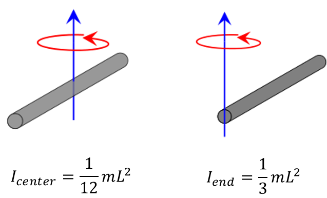
Mass farther from the center of rotation greatly increases the moment of inertia.
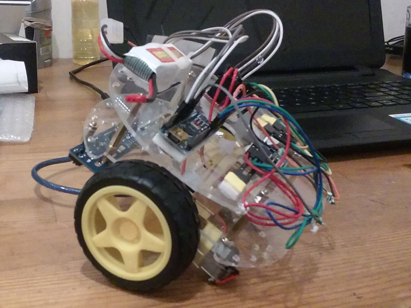
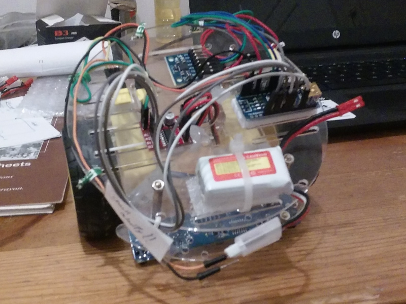
Maximizing the moment of inertia was crucial since the chassis was short and squat, and even a small increase in height would be beneficial. Here’s what the prototype looked like after assembly:
A crude but functional design for testing stabilization algorithms.
The code was developed to provide the necessary stabilization using the MPU6050’s gyroscope and accelerometer. It operates as follows: a complementary filter estimates the pitch angle of the vehicle relative to the horizontal. A PID controller uses this angle to drive towards zero. The output of the PID controller is then fed into a “torque function” that adjusts the command. This function compensates for friction in the motors to ensure that constant inputs generate consistent torque on the vehicle.
To achieve this, the function integrates the control inputs at a specified rate, which keeps the motors running even after a control input is zero. Since control inputs are analogous to the vehicle’s acceleration, this integration provides an estimate of velocity. Similarly, integrating this term offers an estimate of position, which can be used for lateral stabilization. While this method is less precise than using rotary encoders, it serves as a simple and effective workaround.
This approach allows the vehicle’s center of gravity to adjust in real-time, enabling the robot to balance itself and maintain equilibrium. Essentially, there are two PID loops operating simultaneously: one stabilizes the vehicle’s heading, and the other prevents the vehicle from sliding back and forth.
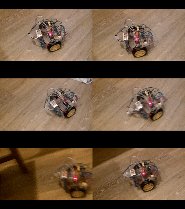
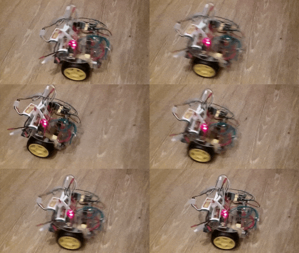
The robot was able to stay upright and adjust for changes in its center of gravity.
Github Repo:
The version of the code associated with this protoype can be found here: SelfBalancingRobot - V1.0
