SB-1 | Updated Self-balancing robot with simpler control algorithm
The initial prototype of the self-balancing robot left me somewhat unsatisfied. While the stabilization algorithm worked, it felt disorganized and improvised. I was concerned that there might be a more efficient way to write a similar algorithm with fewer redundant operations and clearer logic. Additionally, the chassis of the robot could be improved by increasing its height to enhance its moment of inertia. To fully test the stabilization, it would also be necessary to control the robot externally to make it move forward, backward, and sideways. This would stress the stabilization system and reveal how well it handled abrupt state changes.
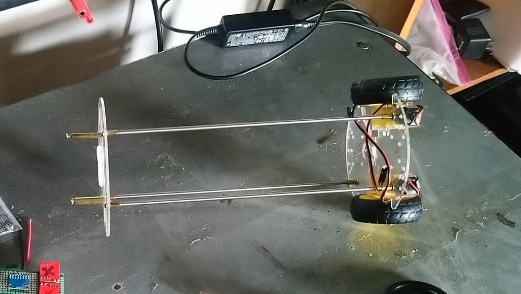
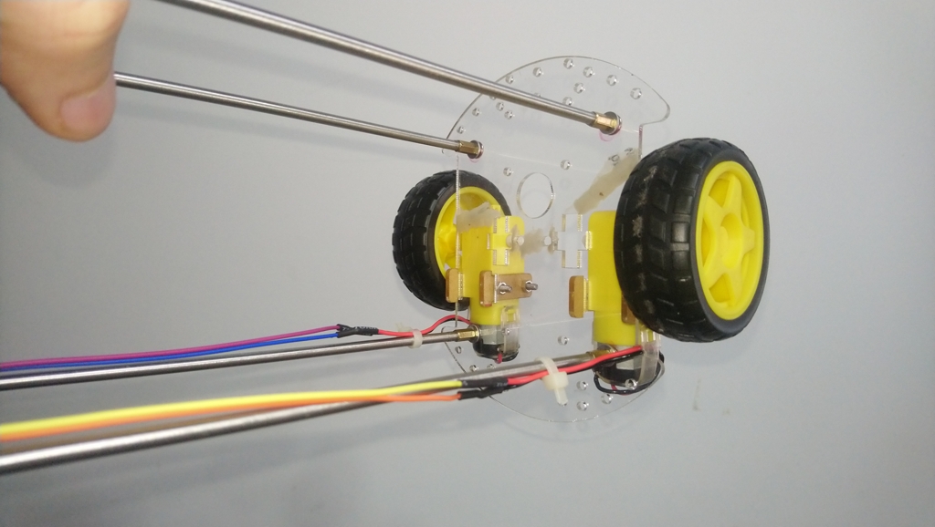
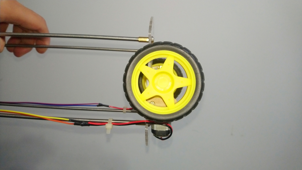
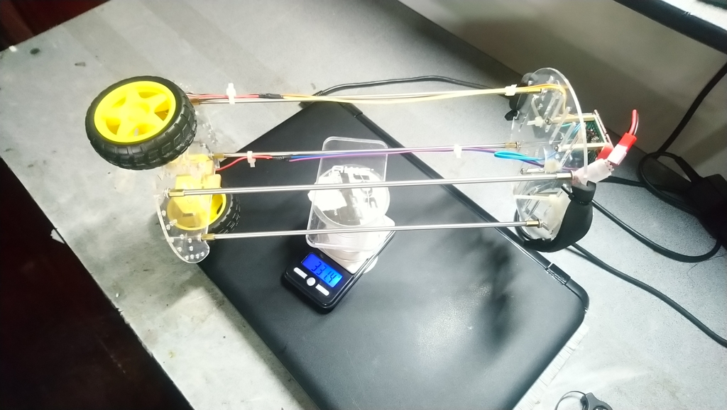
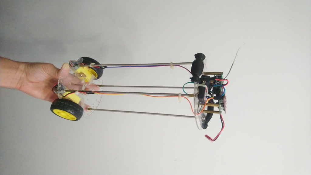
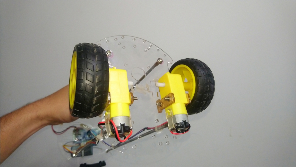
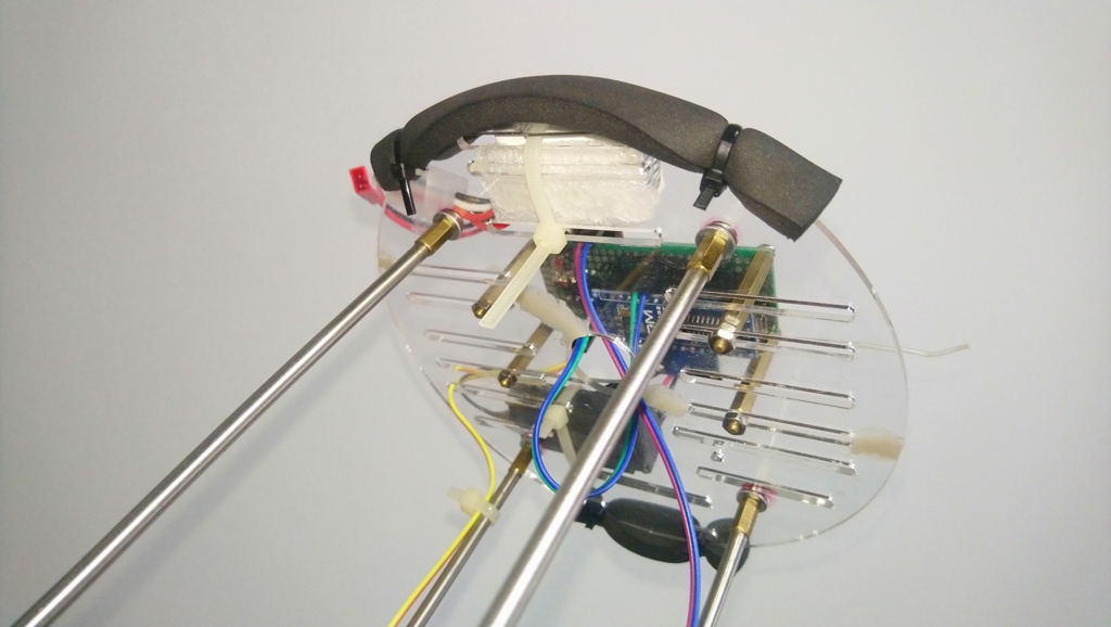
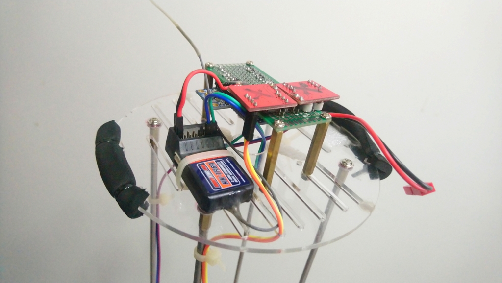
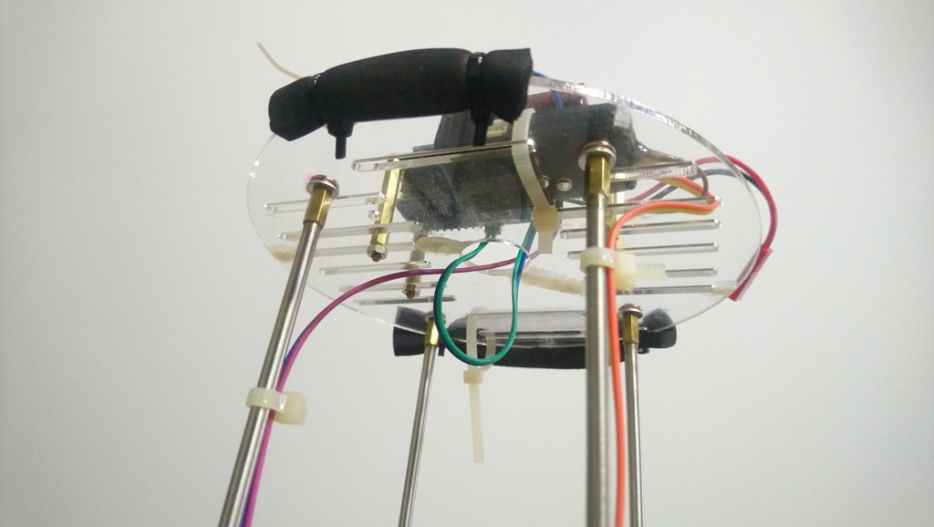
Among these goals, modifying the chassis was the simplest task. It involved replacing the vertical spacers that separated the acrylic sheets with larger ones. The quickest solution I found was to use steel tubes with brass threads glued to each end. This allowed me to easily attach the acrylic sheets to the new spacers without having to alter any other parts.
The extended frame supports increased the moment of inertia
The center of mass was raised relative to the wheels
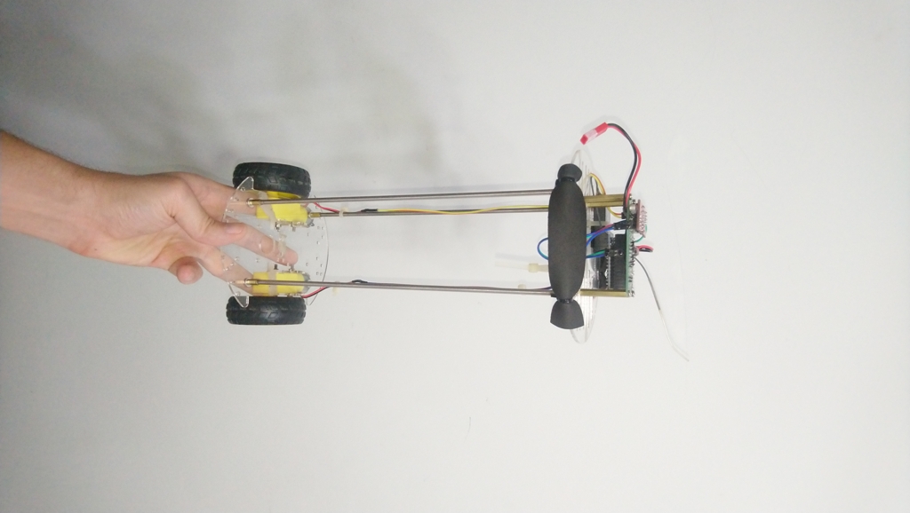
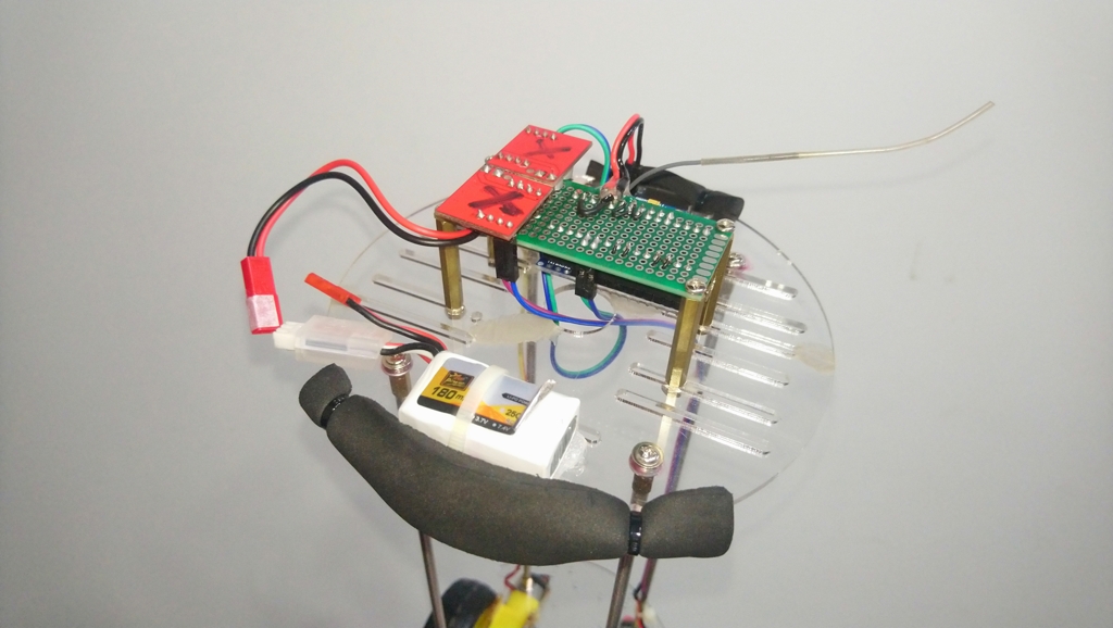
For the electronics, I installed an inexpensive 6-channel 2.4 GHz receiver on the chassis to send control signals to the Arduino. This setup allowed me to use a remote control to guide the robot and test its response. To keep the electronics organized, I soldered every component except the receiver to a prototype board. This way, they could be mounted on the chassis as a single unit and connected via jumper wires to the receiver. Since the receiver was not permanently wired to the robot, it could be reused for other purposes without affecting the robot’s components.
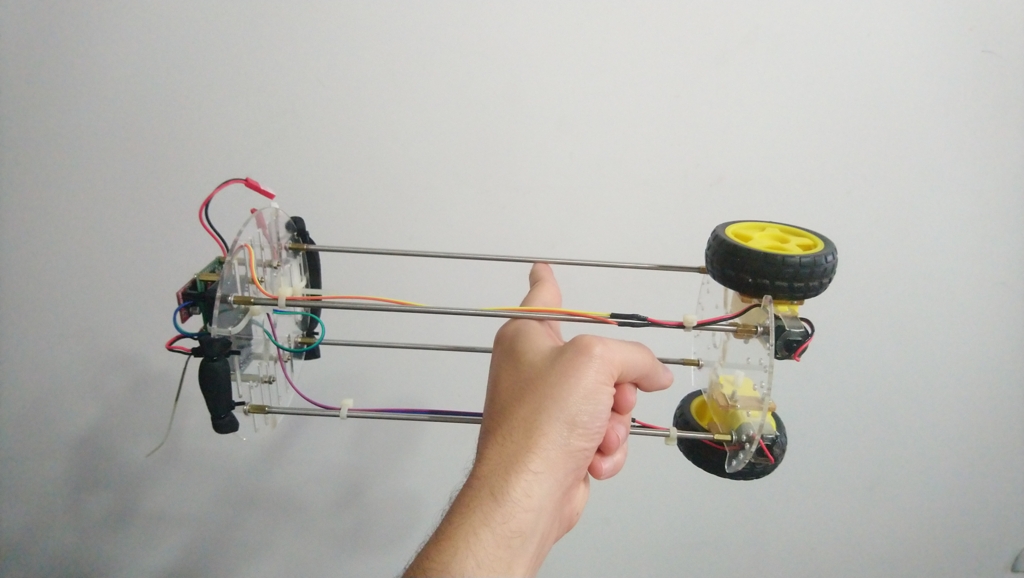
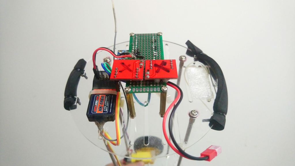
The completed robot had foam pads to cushion impacts when falling
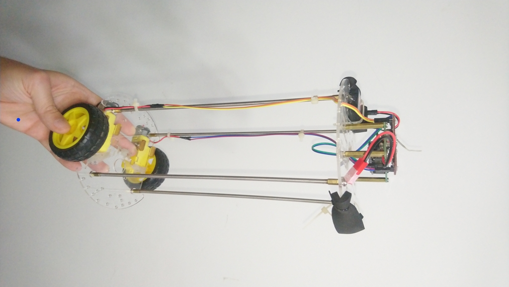
On the prototype board, I soldered an Arduino Nano, an MPU-6050, and two half-burnt H-bridges that I had on hand. Although these H-bridges were intended to drive two motors, they could only drive one motor each. Nevertheless, they worked well enough to drive the motors independently on each side. Here’s what the electronics looked like when mounted on the frame:
Every component was modular in case it needed to be replaced
With the mechanical aspects of the robot completed, I turned my attention to the core of the project: the code and stabilization algorithm. I approached this differently from before by avoiding unnecessary functions. The algorithm uses three PID loops acting simultaneously:
-
Pitch Stabilization: This is the primary PID controller of the system. It uses the pitch angle of the vehicle as a proportional term to keep the vehicle upright by accelerating into gravity.
-
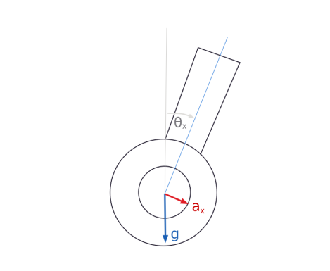
Position Stabilization: This estimates velocity by integrating the pitch angle, which is proportional to the lateral acceleration (at small angles), and integrates it again to approximate position (the double integral of the pitch angle). Both are used as the derivative and proportional terms, respectively. Their combined effect prevents the vehicle from drifting laterally and counters any change in the center of gravity.
-
Yaw Stabilization: This controller maintains heading by using the angular velocity of the yaw axis as a proportional term. It counters the open-loop nature of motor control, where one motor can spin faster and cause the vehicle to turn.

Position and velocity can be estimated by integrating the bank angle
Ultimately, the unstable axis is stabilized only by the measured pitch angle. Yaw stabilization is necessary to maintain a fixed heading, as asymmetries in the motors would otherwise cause the robot to turn if controlled symmetrically.
Both motors are driven with pulse frequency modulation to counter magnetic cogging and stiction. The duty cycle is long enough so that each pulse causes the motors to rotate one magnetic pole. This waveform provides precise control over low-speed rotation at the cost of jerky movement. This precision is necessary to minimize under- and over-correction when the vehicle is nearly vertical. Driving the motors this way makes them behave similarly to stepper motors, though with less precision, larger steps, and reduced torque.
The control algorithm incorporated two inputs from the radio receiver: one to set the target velocity of the robot for forward and backward movement, and one to set the rate of angular velocity. The receiver’s signals were decoded using pin change interrupts on the Arduino to measure pulse width. The pulseInput library is a flexible example of how to read such signals. With all these factors combined, the robot performed quite well. It was significantly smoother than the first iteration, thanks to the improved stabilization algorithm and increased moment of inertia:
The robot was capable of maintaining balance and being guided via remote control
Overall, I’m pleased with the results. Although it’s far from perfect and not as refined as more popular control methods involving stepper motors, this project demonstrates a valuable experiment and clever software workaround. If the same algorithm were paired with better motors (such as brushed coreless motors that suffer from less stiction and cogging), it’s likely the robot’s performance would improve significantly. At the very least, it would have a much smoother response due to the reduced minimum torque required to rotate the wheels.
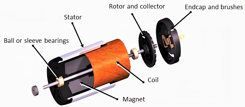
Coreless brushed DC motors have iron-less rotors that do not cause cogging
GitHub Repo
The version of the code associated with this prototype can be found here: SelfBalancingRobot - V1.2
