Custom servo motor using a DC motor, H-bridge, and an analog sensor
In the process of developing a servo-powered ornithopter, I had the misfortune of damaging multiple servos while experimenting with higher voltages. Unfortunately, the boards that drove the servos were incapable of operating at those higher voltages, and their motor controllers burned out. I was left with servos that were mechanically intact but electronically damaged. To make use of their perfectly fine mechanisms, I opted to control the servos with an Arduino. This would allow me to reuse them and provide the flexibility to safely increase the voltage. I could choose a motor driver with a maximum voltage much higher than what the servos were originally intended for. An inexpensive H-bridge can easily operate up to 12 volts, while a servo generally operates between 5 and 9 volts. With this flexibility in mind, the library was written to be a drop-in replacement for the stock controller boards, assuming one had the following equipment:
- An Arduino
- An H-bridge
- A DC motor that can be reversed by flipping the voltage across it (this is normally a brushed motor)
- An analog sensor that can measure the position of the motor
The Arduino needed to have an unused analog input pin and two digital pins capable of PWM output. Each of the components had to be connected in the following way:
- The motor leads connect to the H-bridge.
- The H-bridge input pins are connected to the chosen PWM pins of the Arduino.
- The sensor is connected to the chosen analog pin of the Arduino.
- A voltage source is connected to the H-bridge and Arduino. This could be anything that does not exceed the safe limits of both devices.
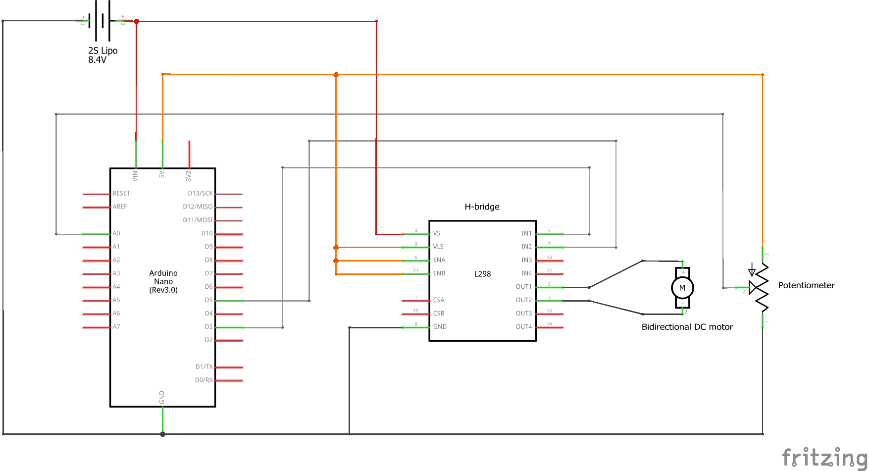
Schematic of the required connections
Note: The library used analogRead() to measure the sensor. As such, the entire range of motion would be divided into 1024 individual steps. For a 180-degree rotation, this means a maximum precision of 180/1024 ~ 0.18 degrees.
The motor output was controlled via a PID controller. To reduce the overhead in storing constant values, the associated coefficients were set when the sketch was compiled and could not be changed once the Arduino was running. With these coefficients, it was possible to obtain very smooth signals for the derivatives of the servo’s position. Without this information, it would have been very difficult to create the PID controller because of the stepped nature of the position measurements. These discrete jumps greatly increased the noise of any derivative, so smoothing had to be implemented to ensure a good approximation. Credit goes to Pavel Holoborodko for the coefficients used to calculate the derivatives. See his work on noise-robust differentiators.
Video of a hobby servo that is controlled using this library
Once the PID coefficients were tuned correctly, the servo controller was capable of very precise and smooth motion. Obviously, it was not as precise as the original circuit inside the servos, especially in the case of digital servos, but it was certainly usable for many applications. It was also possible to arbitrarily raise the voltage of the servo and readjust the PID coefficients to prevent over-correction, which is something that pre-built servos are incapable of doing unless they are programmable.
GitHub repository
The servo library can be downloaded directly from its GitHub repository. It can also be downloaded from the Arduino library catalog. Alternatively, you can download it from the original RCgroups post. Please see the following links: