Review | Ornithopter powered by a motor with a crank-shaft
Introduction
Ornithopters are fascinating aircraft in that they are capable of mimicking animal flight by flapping their wings to stay aloft. This type of motion can be accomplished through a multitude of different mechanisms. One such approach is to use a crank shaft that converts rotary motion into reciprocating motion. An example of this mechanism is a piston engine, wherein a shaft connected through a crank moves a piston back and forth. A great advantages of using a reciprocating mechanism is that it allows the motor that drives the entire mechanism to rotate continuously in one direction.
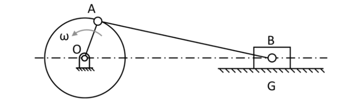
A crank can be used to convert rotaty motion into reciprocating motion
This is very efficient as it allows the motor to operate in a single direction at an ideal torque and angular velocity. By comparison, a reciprocating motor cannot obtain this efficiency as the motor is constantly forced to change direction, having an angular velocity and torque output that changes with time. While a reciprocating drive can easily adjust the motion of its output by simply changing the commanded velocity at which it rotates, along with the direction in which it moves in, a crank mechanism cannot do this. It is restricted to moving in the waveform generated by mechanism based on the rotation of the input motor. Therefore, we can see that a crank-based system exchanges controllability for efficiency compared to a reciprocating system that gains controllability but loses efficiency.
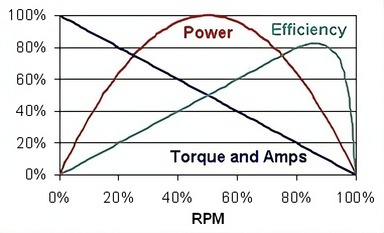
Electric motors obtain maximum efficiency at a specific speed
Motivation of project
In the process of developing a servo-based ornithopter that used reciprocating motors to drive the wings, it became obvious that the inefficiency of the system made it much more difficult to attain flight. In an effort to separate the problem of developing an efficient set of ornithopter wings versus generating a reciprocating drive that had enough power to attain flight, I focused on making an ornithopter that was powered through a crank mechanism.
Design iterations
Iteration 1:
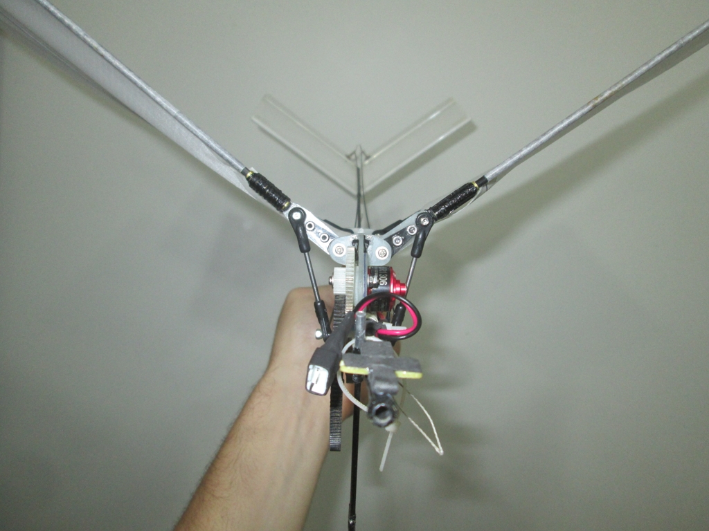
The first iteration of the motor-powered ornithopter was very simple and consisted of a set of tubes that were joined together to make a frame. The wings were driven by a two-stage gearbox that connected to a crankshaft, that then drove a set of wings through a reciprocating conrod. A transverse crankshaft was chosen because of the direction it would generate any resulting torque from the motor. In this mechanism, the crank rotates in an axis that is at 90 degrees from the axis of rotation of the wings. This configuration makes the conrod move in two directions, meaning that it cannot be mounted on single-axis bearings, but must be mounted on the equivalent of ball and socket joints. These joints tend to increase the friction of rotating the crank mechanism. The transverse configuration ensures that the oscillation of the wings remains symmetrical.
A transverse crank ensured symmetrical wing motion
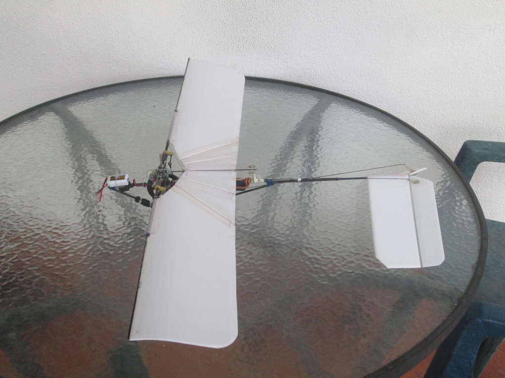
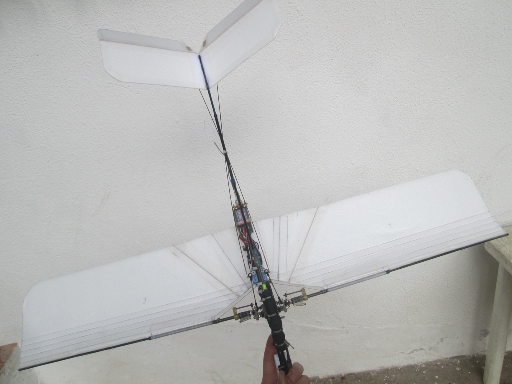
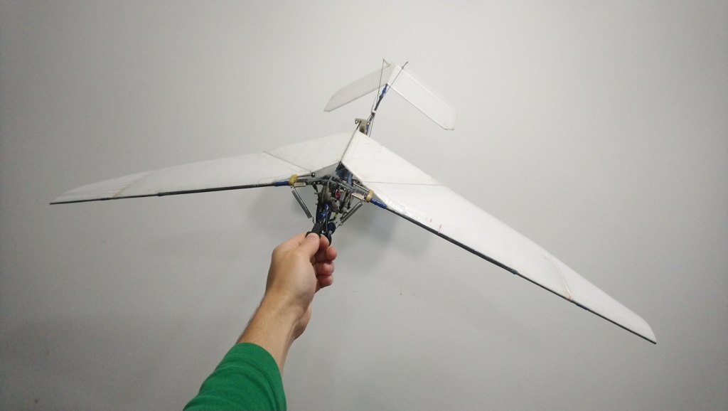
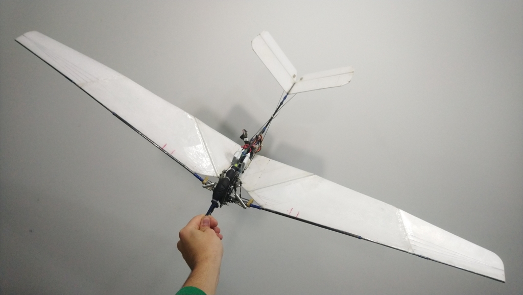
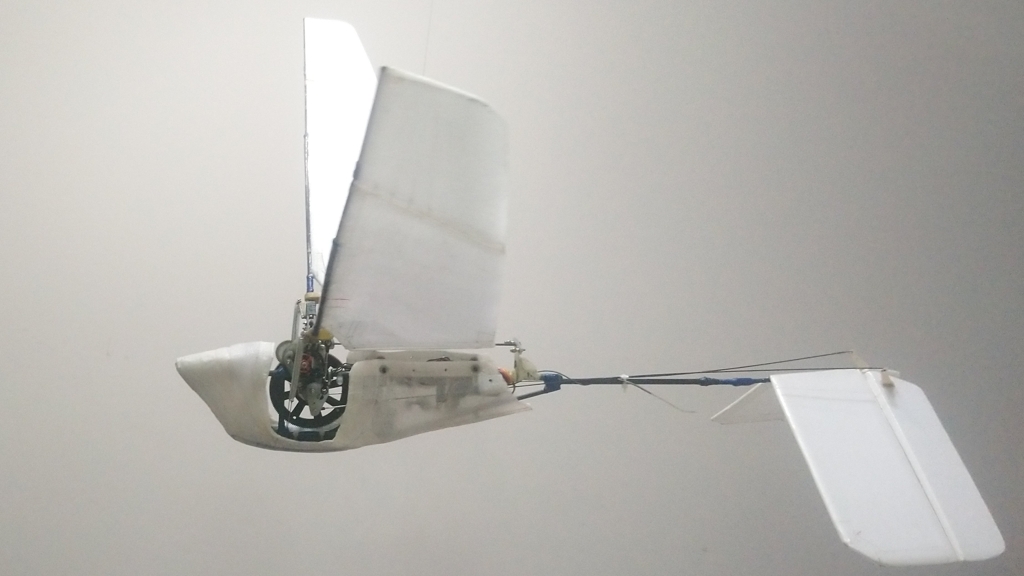
To further increase the simplicity of the ornithopter, the wings and the tail were given a rectangular planform. The tail was initially built in an upright V-tail configuration, but unfortunately this configuration proved to be very inefficient at changing the direction of the aircraft. On the other hand, the wings, along with the motor and crank system, proved to be sufficiently powerful to keep the aircraft aloft, albeit with a very marginal rate of climb. To improve the control authority, the tail was rotated 180 degrees so that it faced downward. This inverted V-tail proved to be far more effective at changing the direction of the aircraft.
The initial version had an upright v-tail
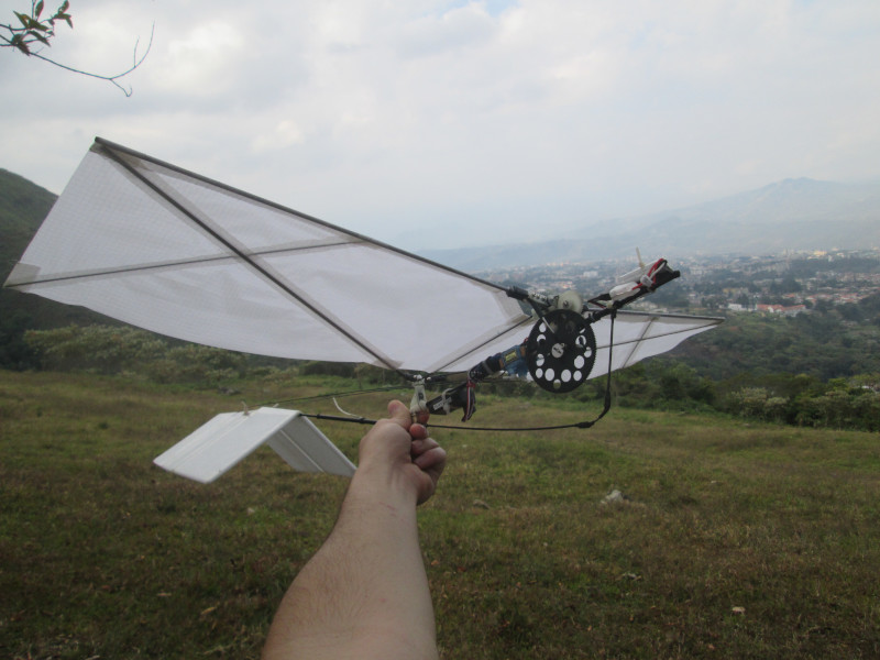
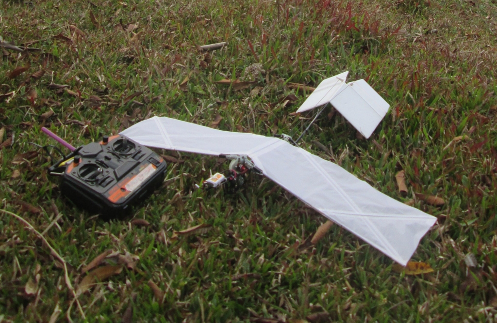
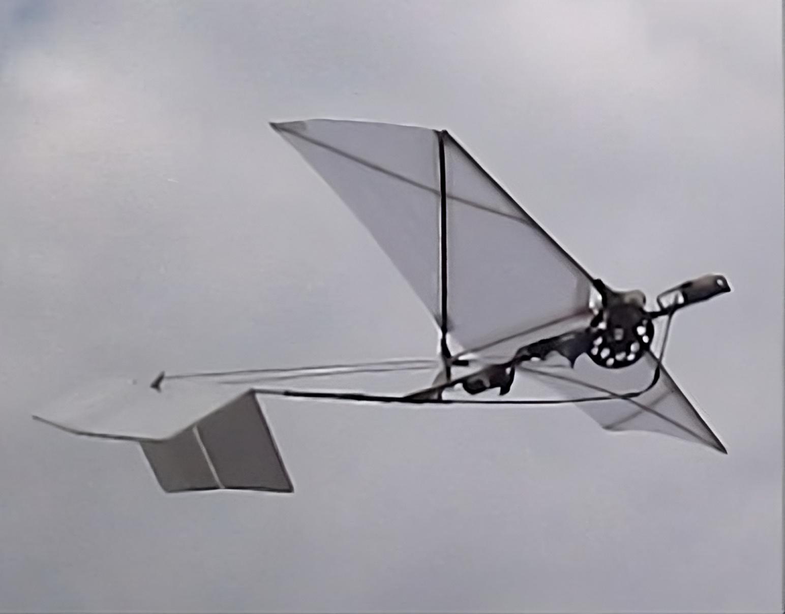
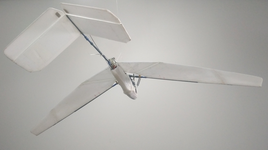
An inverted v-tail greatly improved handling
The controls were now very efficient and aggressive, and it was even possible to overcorrect based on the control deflections that were established before. To increase performance of the wings, the diagonal spars that were initially installed on the wings were replaced with thicker beams than increase the torsional rigidity of the wing. This had the effect of significantly increasing the climb rate of the aircraft, the end result being a machine that was capable of aggressively turning and maintaining altitude while climbing at a reasonable rate.
Video 1. Ornithopter with inverted V-tail
Iteration 2:
In an another effort further improve the wings, both in terms of the thrust they produced and the lift they were capable of generating, a set of ribs were installed along their span. The ribs close to the root of the wing were bent to provide an undercambered airfoil, while the ribs near the tip of the wing were left flat to provide a symmetrical airfoil.
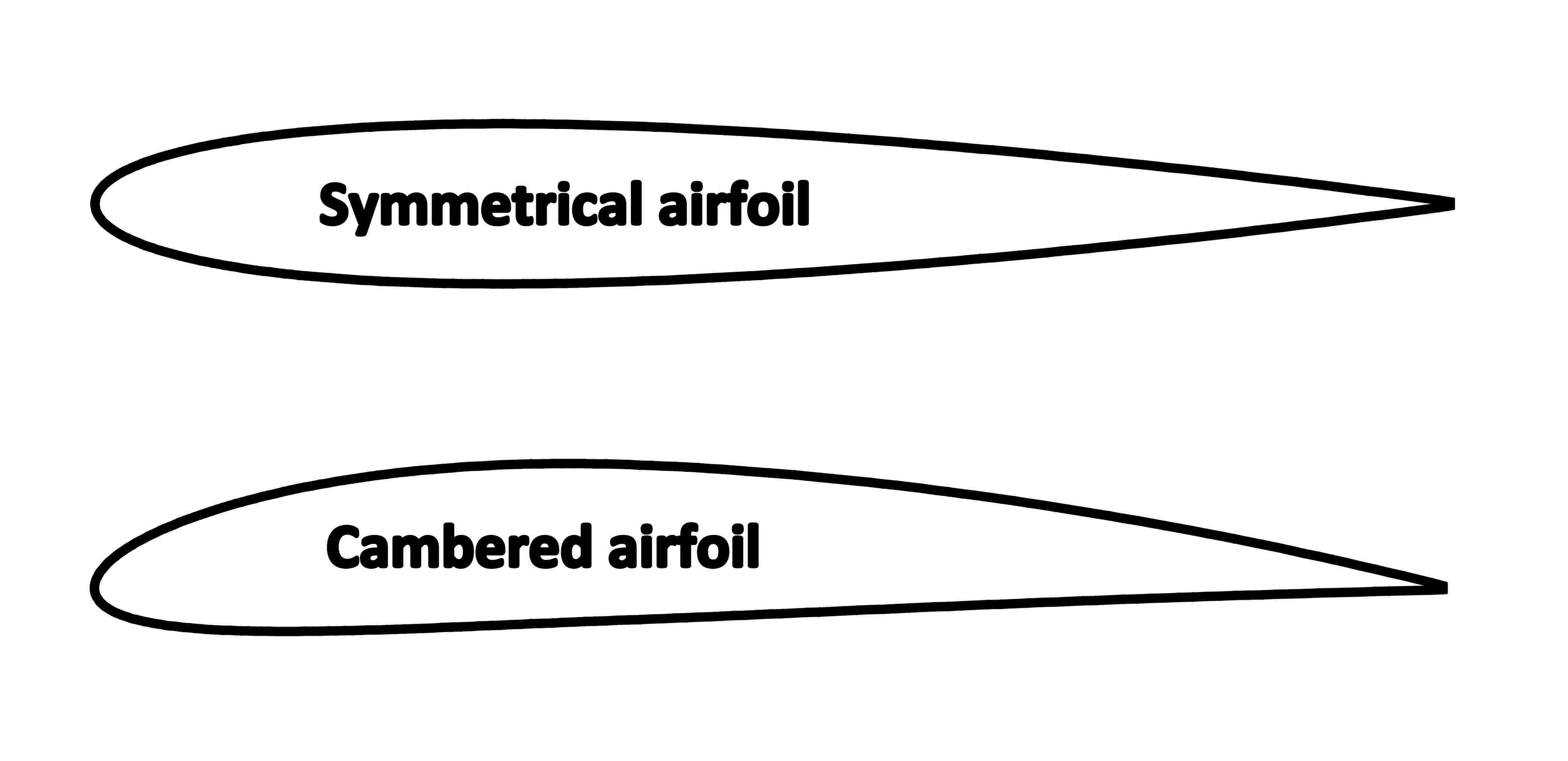
The logic behind this configuration was that airflow at the root of the wing would not be affected greatly by the tangential velocity generated by the wing oscillation. As such, the root sections of the wing could focus on generating lift to counter the weight of the aircraft. On the other hand, since the wingtips were greatly affected by the tangential velocity, they would most likely see a reversal of angle of attack during the upstroke. Under these conditions, a symmetrical airfoil is better suited because it can efficiently generate lift indifferent of whether the angle of attack is positive or negative, therefore maximizing the thrust generated by the wingtips.
The modified wings had ribs with and without camber
An additional modification was the addition of strong downstroke springs. These springs would bias the torque felt by the entire crank mechanism while the aircraft was in flight. Rather than seeing a large load during the downstroke and a sudden loss of load during the upstroke, the bias springs would even out this asymmetry, making the motor feel a roughly constant resistace indifferent of whether the wings are moving upwards or downward.
Video 2. Cambered wings and bias springs
While these modifications appeared to be very good on paper, in practice, they barely had an effect on the performance of the ornithopter. In fact, it almost felt like they had a detrimental effect on the performance.
Iteration 3:
Unsure of what else to do, I focused on changing the characteristics of the wings in an effort to decrease the power needed to keep the ornithopter in flight. These experiments involved changing the planform of the wing along with trying out different diagonal spars that would affect the torsional rigidity of the wings. After multiple iterations, the most successful wings had relatively flexible diagonal spars with a bend in at middle that generated wash-in (the opposite of washout) at the wing tips.
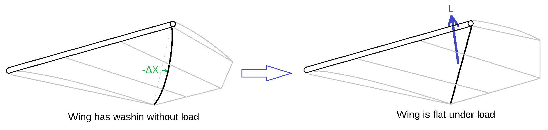
Pre-bent diagonal spars counter twist due to weight
This inbuilt twist meant that when the wings were not loaded, tips would have a degree of downwards twist. But once the wings began to generate lift, tips would rise, making the entire wing have almost no twist when carrying the weight of the aircraft. This was a finely tuned configuration, meaning that any increase or decrease in the weight of the aircraft would bias the twist of the wings while in flight. Another modification to the ornithopter was a reduction of the incidence angle of the tail with respect to the wings. This meant that the wings would operate at a lower angle of attack, which would force the ornithopter to fly at a higher airspeed.
Pre-bent diagonal spars twisted the wingtips when unloaded
Video 3. The pre-twisted wings allowed the ornithopter to glide and fly better
The end result of these modifications was an aircraft that flew faster and had a slightly higher rate of climb compared to its original configuration. It was also capable of gliding much better which was a welcome benefit. The wings were configured to hold a particular dihedral angle thanks to the downstroke springs that would prevent them from collapsing under load.
Iteration 4:
Despite this multitude of iterations and experiments with the wing design, it became clear that after a point the modifications did not have an effect. Moreover, increasing the flapping frequency of the wings by means of adding a higher voltage battery to drive the motor, didn’t seem to have the impact that one would expect. It did not greatly increase the rate of climb of the aircraft, and to some extent it seemed like flapping the wings faster tended to hurt the rate of climb, as the aircraft would tend to fly slower. This behavior suggested that the propulsive efficiency of the ornithopter decreased as the flapping frequency went up. The aircraft didn’t fly any faster or climbed any better when the motor was outputting more power.
Inertial forces act to decrease thrust with increasing frequency
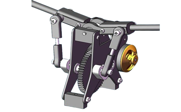
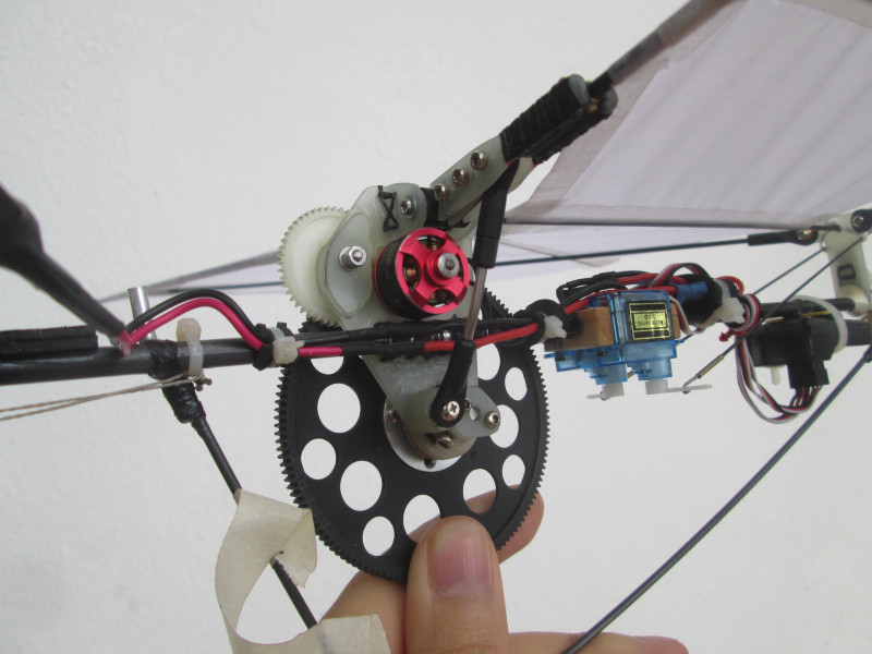
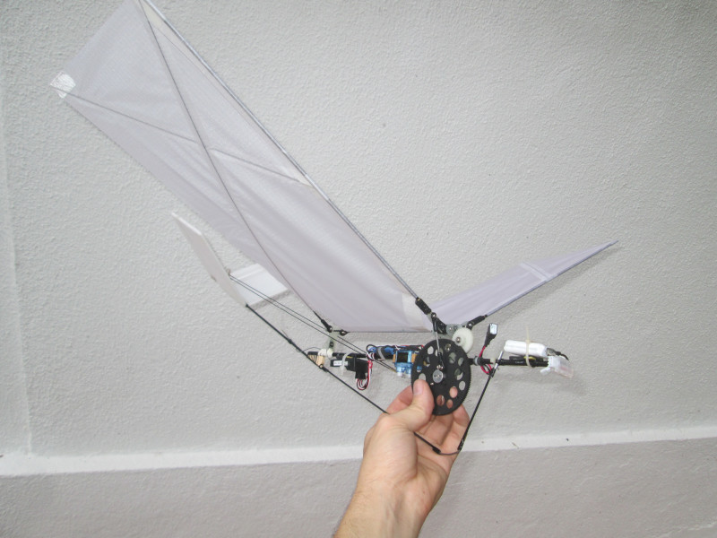
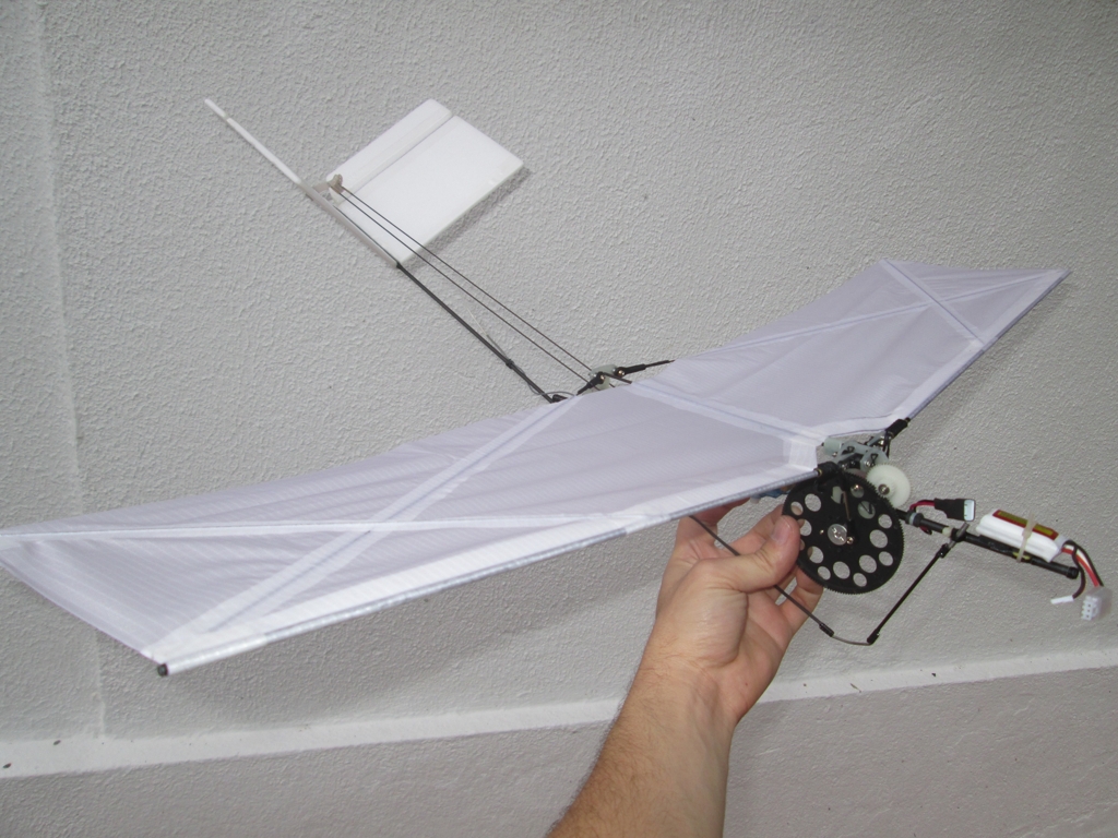
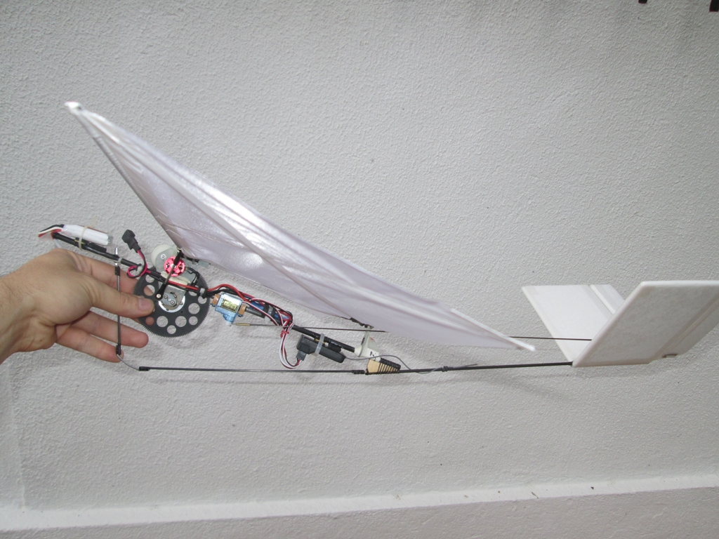
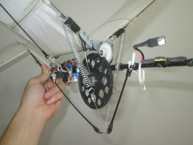
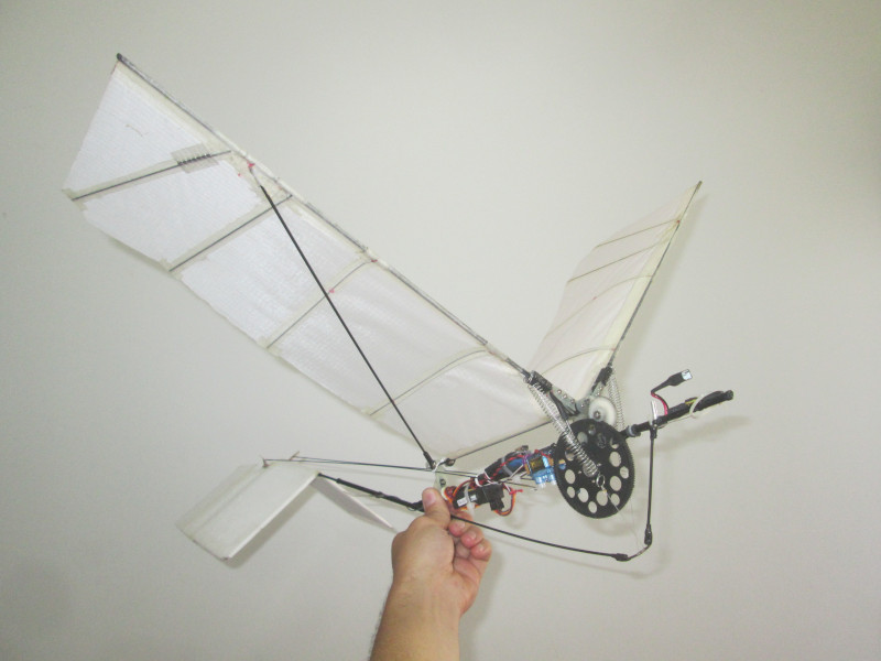
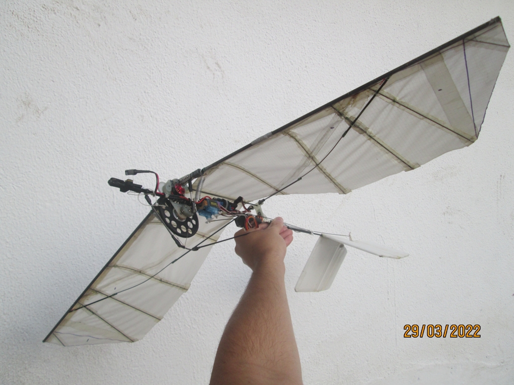
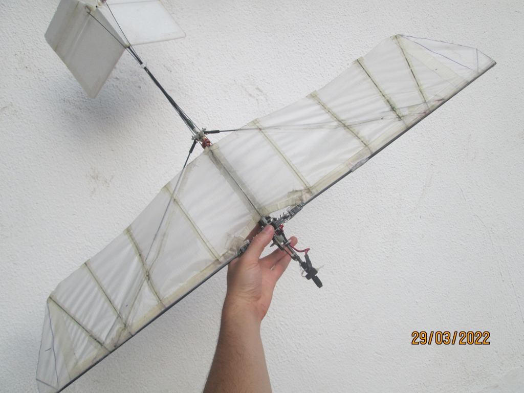
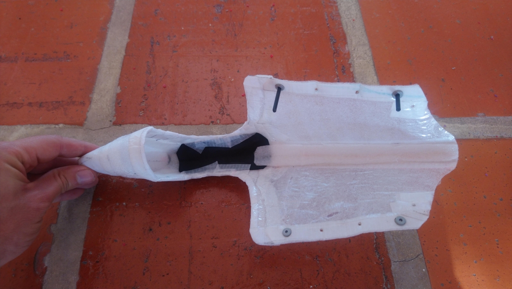
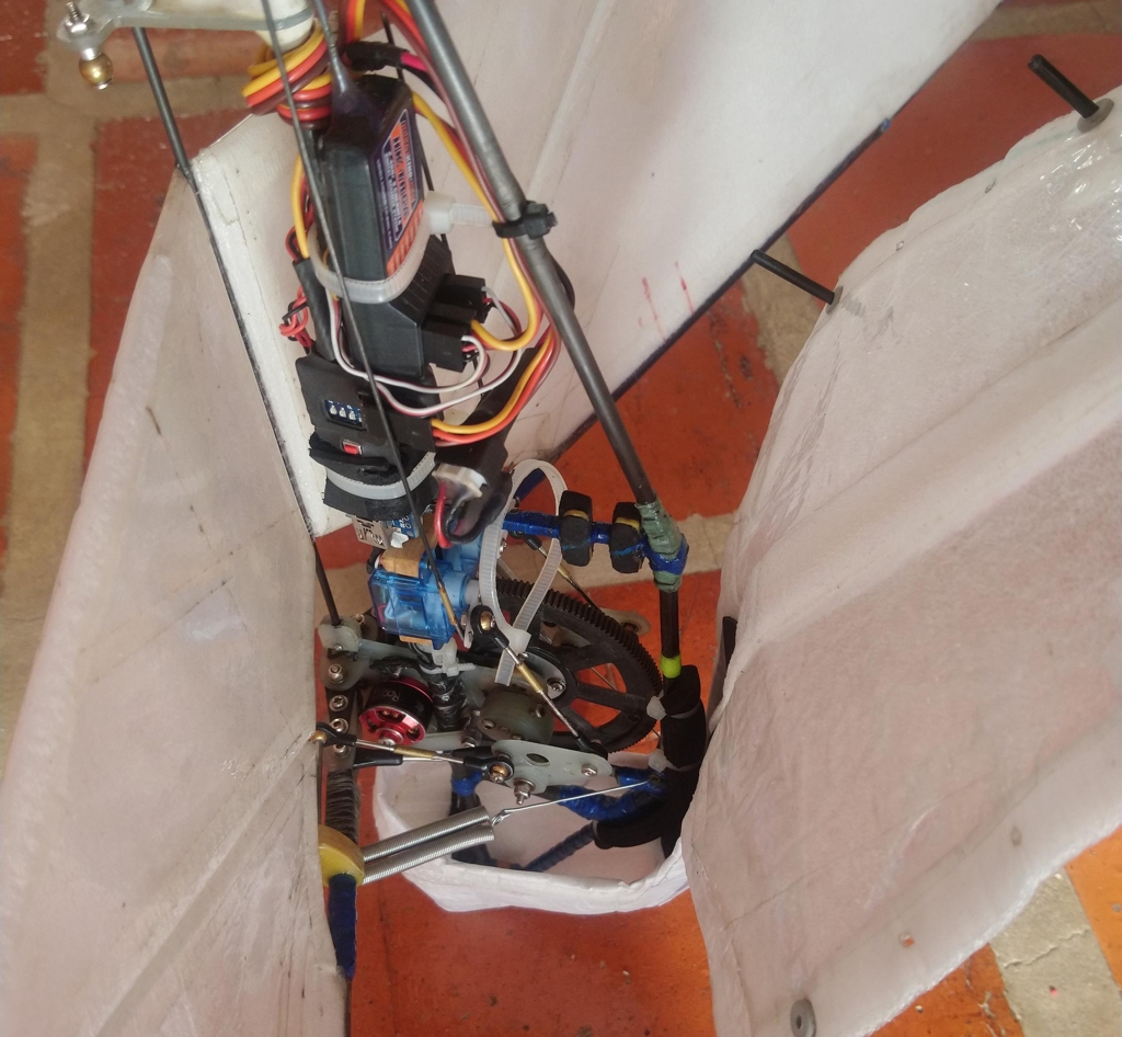
After some mathematical analysis, it was deemed that perhaps the passive nature of the previous wings was the culprit of this observed plateau in performance. Rather than depending on the forces acting on the wings to twist them in such a way that they would produce thrust, a mechanism could be used to force a particular twist profile as the wings oscillated to ensure their kinematics did not change with frequency. To accomplish this motion, a simple mechanism was developed that could attach to the existing transverse crank that could oscillate the spars of the wings. The flexible membrane wings are also replaced with rigid foam panels that greatly increased the rigidity of the wings without making them incapable of being rotated by the spar twisting mechanism.
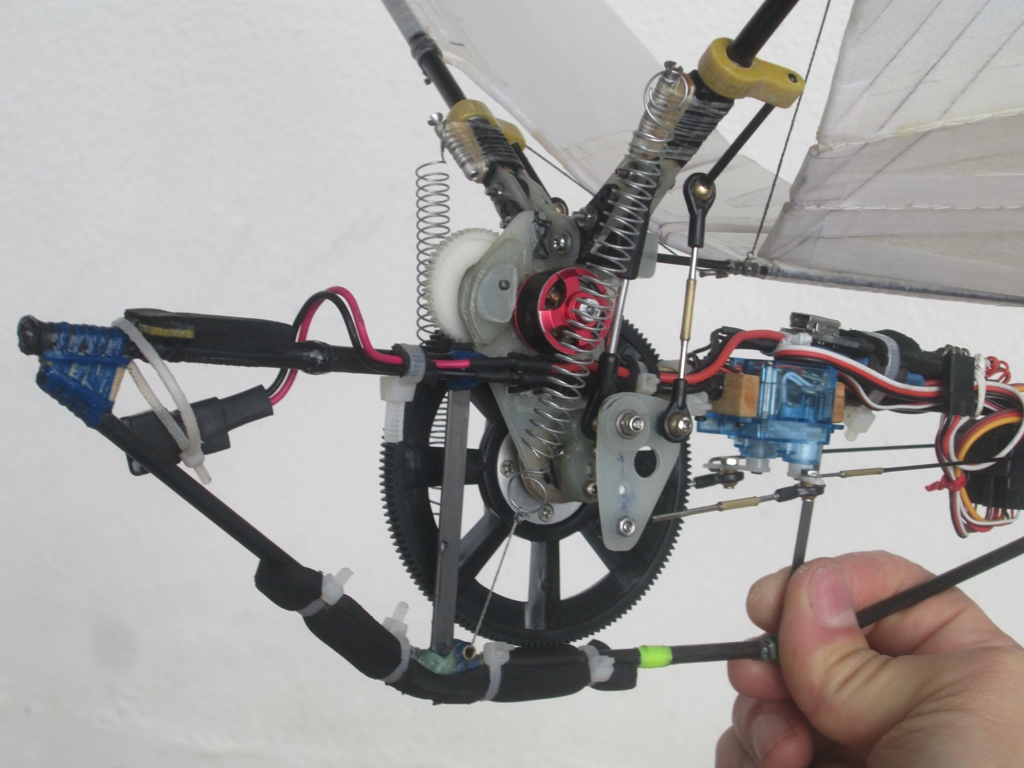
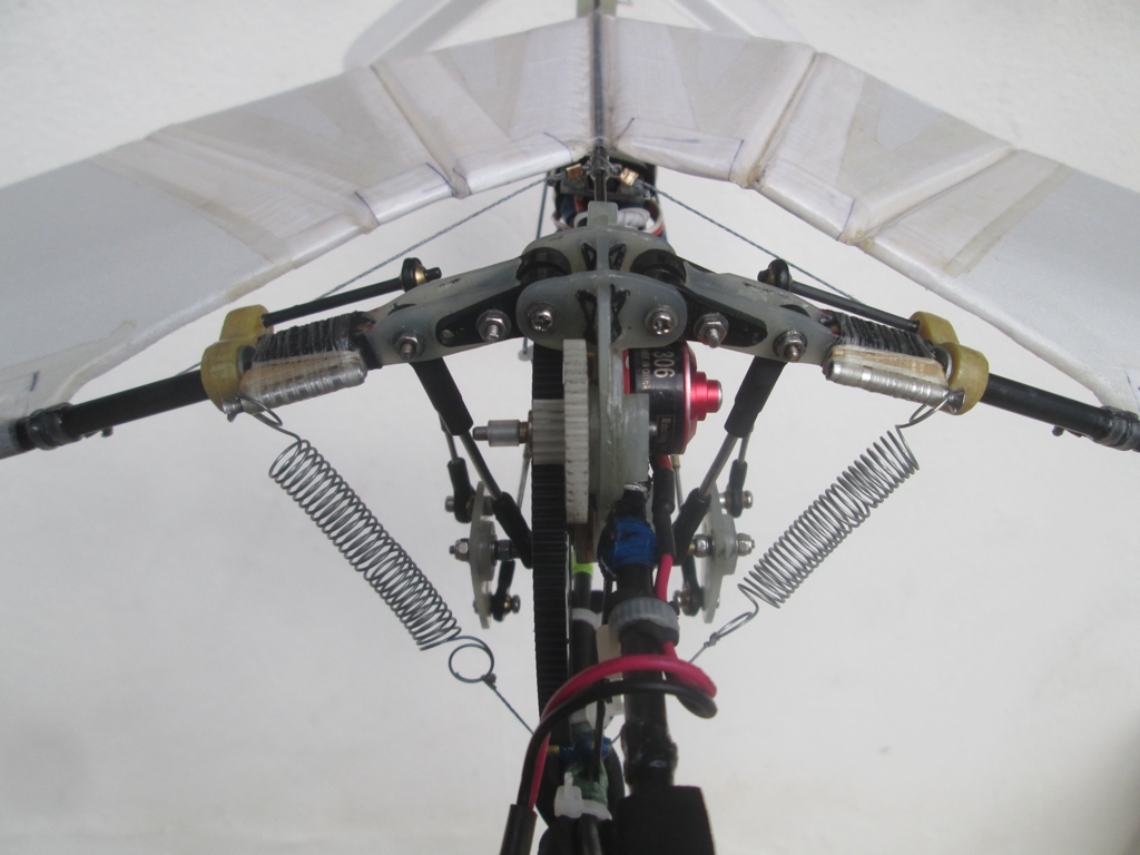
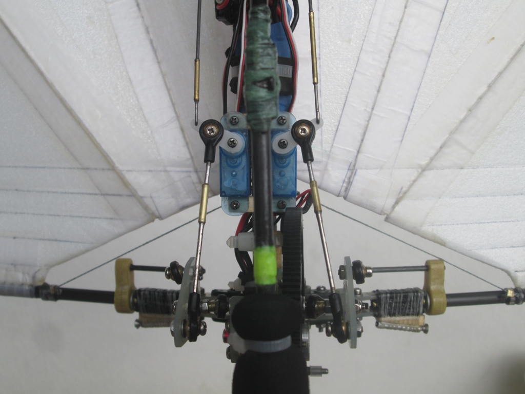
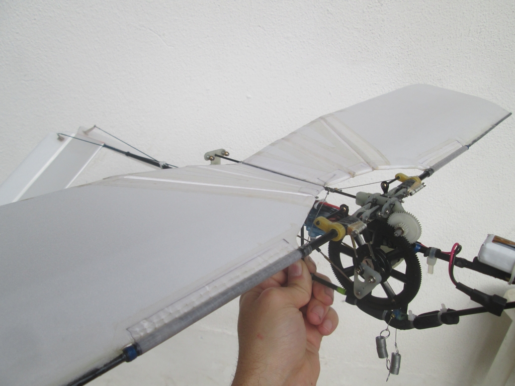
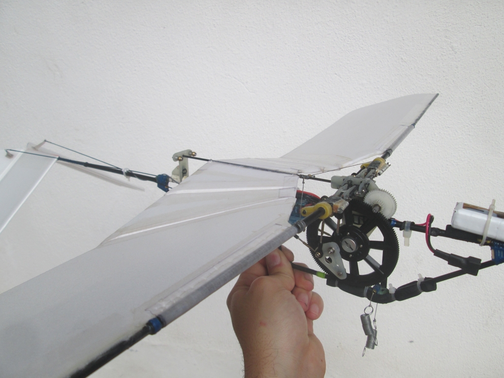
The active twist mechanism built upon the transverse crank
The initial foam wings had a simple rectangular planform
These modifications increase the weight of the aircraft, so the battery voltage was raised to compensate for the additional power that was expected to be needed. The end result was an aircraft that, despite being heavier than its original iterations, flew faster and could climb more aggressively than before. It did, however, flap its wings at a noticeably higher frequency, which indicated that the active twist mechanism played its part by increasing the propulsive efficiency across a wider range of flapping frequencies.
Video 4. Active twist with simple rectangular wings
Iteration 5:
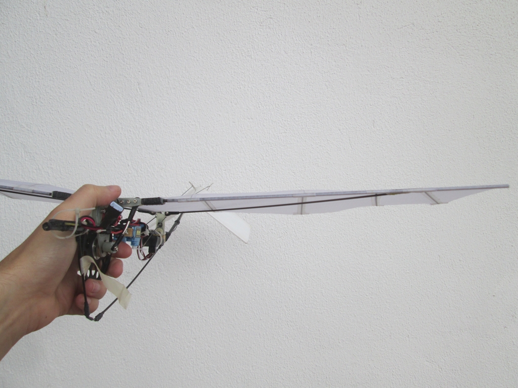
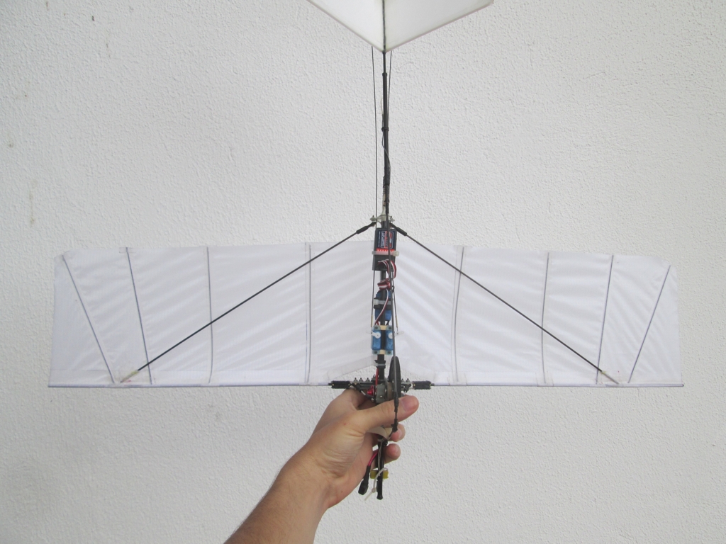
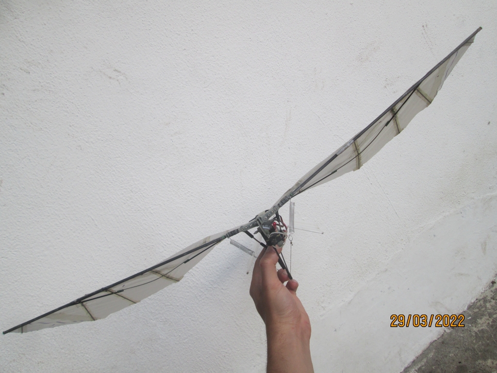
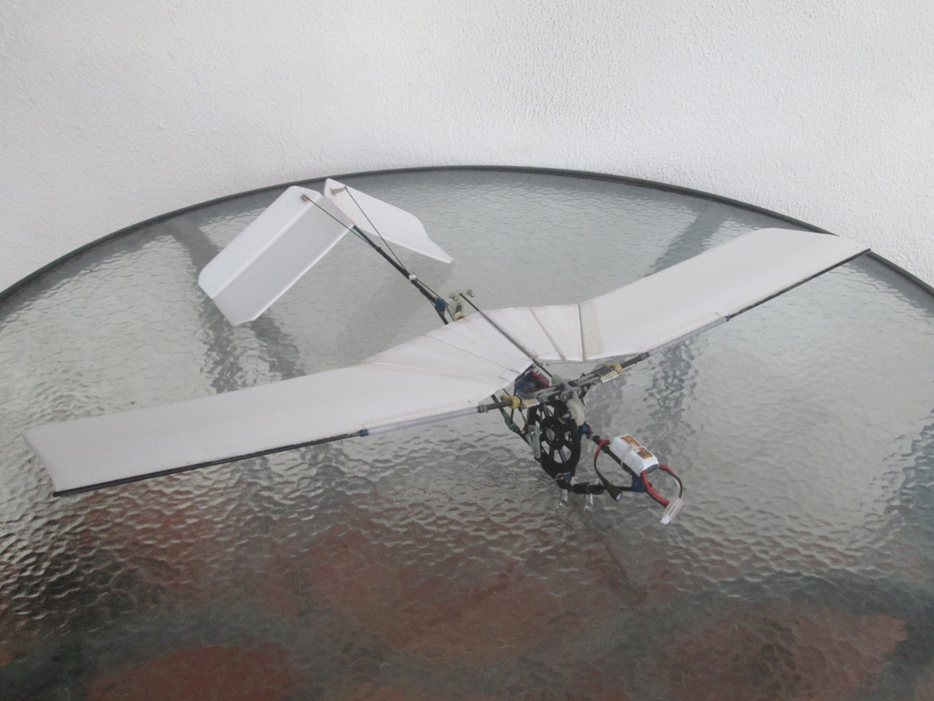
Unfortunately, the higher loads generated by the increase in flapping frequency, along with the greater weight of the aircraft, made the wings and crank mechanism fail on multiple occasions. It was also observed that the performance of the aircraft began to decay after multiple flights. Its unclear why this happened, but a combination of gearbox ware along with degrading batteries likely played a role. In an effort to decrease these loads and to further increase the performance of the aircraft, a series of experiments were begun to modify the shape of the foam wings. After multiple experiments with different planforms, along with variations in the amplitude at which the wings flapped, it was identified that long wings with tapered tips provided the best performance.
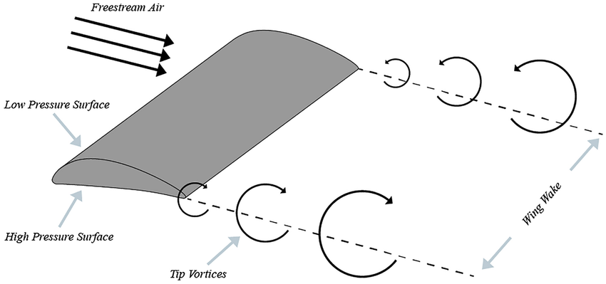
Induced drag reduces the thrust generated by the wing-tips
This was likely due to two reasons. Longer wings move the tips farther out which increases their tangential velocity and thus increases the thrust they produce. Since the tips are acting as the propeller region of the wings, it’s also beneficial if they have a high aspect ratio to decrease as much as possible the induced drag they generate. This requires that the wings become progressively narrower at the tips. Moreover, by decreasing the area of the wingtips, there is less mass being accelerated in that region, so the entire moment of inertia of the wing is decreased. The end result is that these long thin wings with tapered tips can generate the same amount of lift and thrust for less power than short and broad wings.
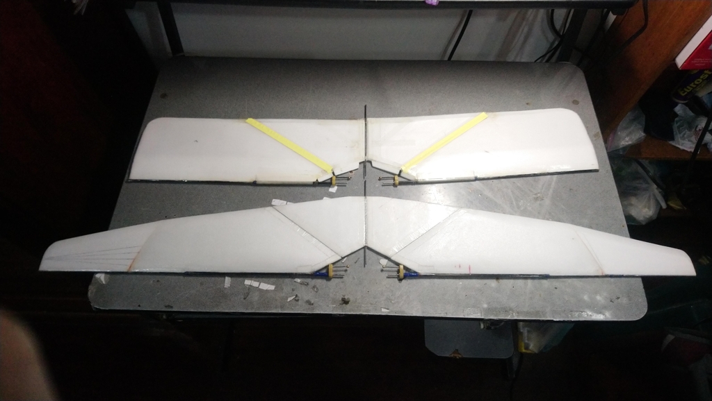
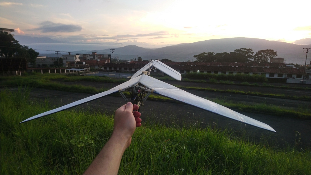
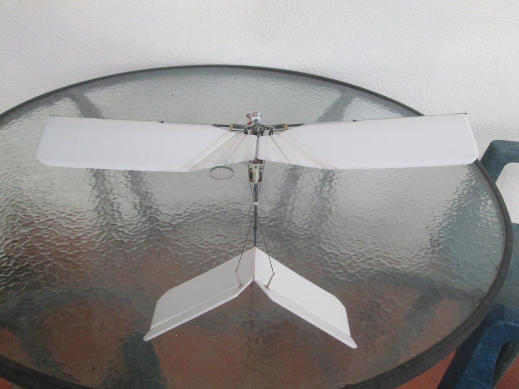
Long tapered wings provided the best performance
Despite longer wings having a larger moment of inertia because of their increase in radius, the increase in thrust generated by that extension tends to compensate for the greater ammount of energy lost by constantly accelerating the wings (inertial loss). As consequence, it is still beneficial to have longer wings than shorter wings despite the opposition of these effects.
Video 5. Highly tapared tips with active twist
When put in practice, these long, thin wings had a significant impact in the performance of the ornithopter. It flew faster, longer, and had a slightly increased rate of climb. It was also observed that the flapping frequency decreased, indicating a potential decrease in the stresses experienced by the flapping mechanism as the wings weren’t being accelerated as quickly.
Iteration 6:
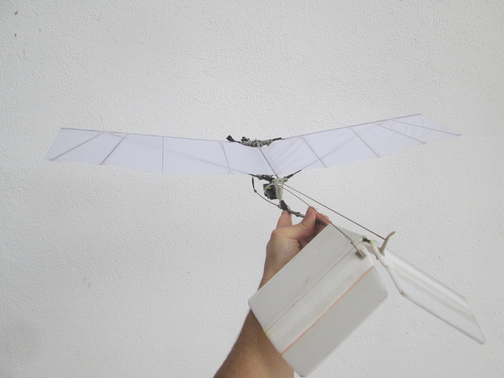
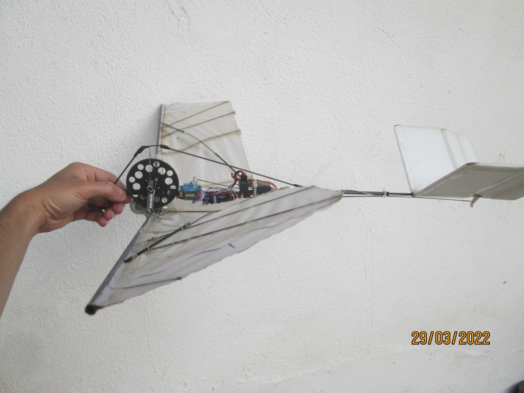
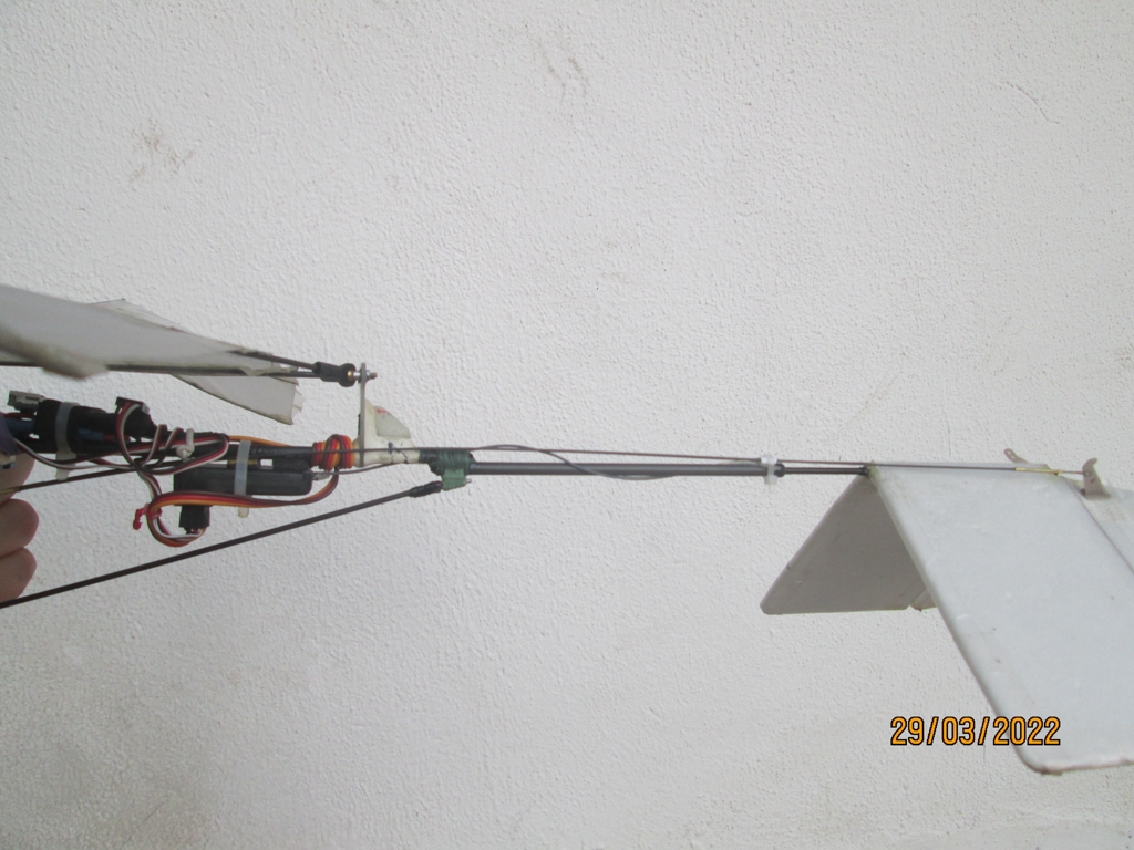
To further increase the performance of the ornithopter, a cowling was built that could wrap around the existing fuselage in an effort to decrease the parasitic drag of the aircraft. This increased the weight of the aircraft and hence the power it would require to maintain flight, but the decrease in drag caused by the cowling was expected to more than compensate for this effect. This assertion was proven to be correct, as the aircraft had a noticeable increase in performance.
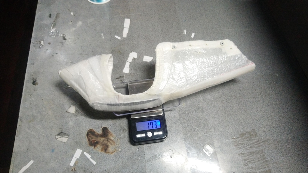
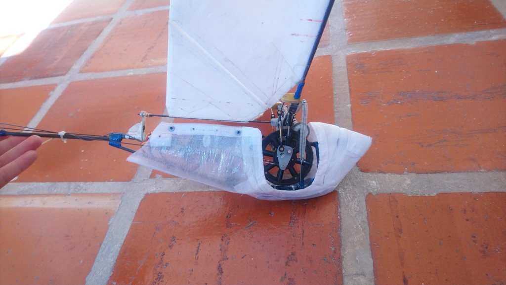
The cowling had a sock-shape and wrapped around the fuselage
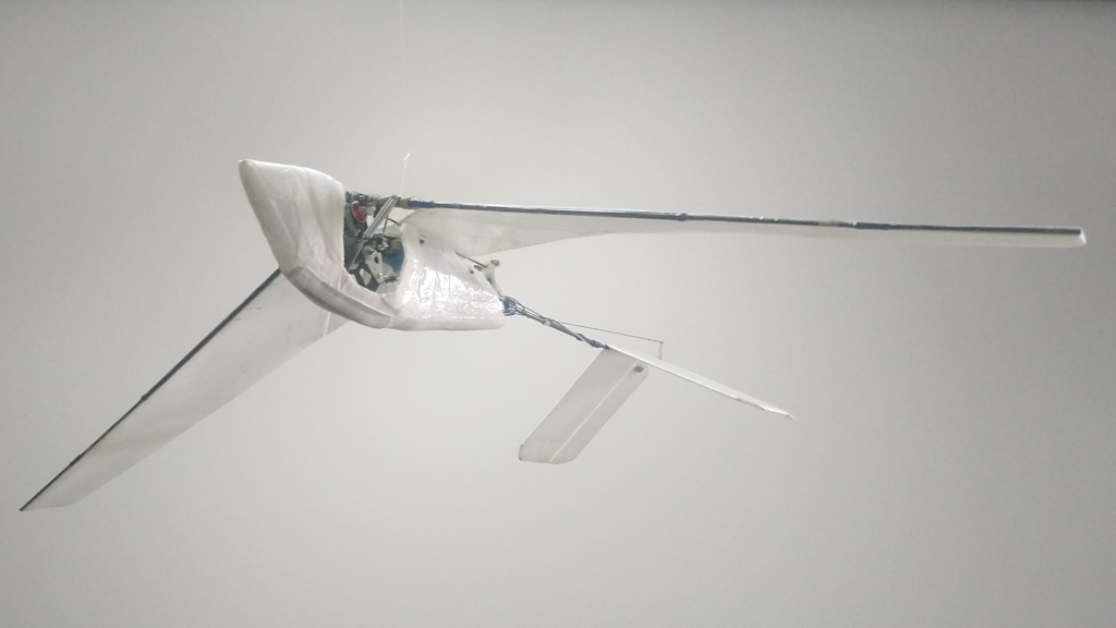
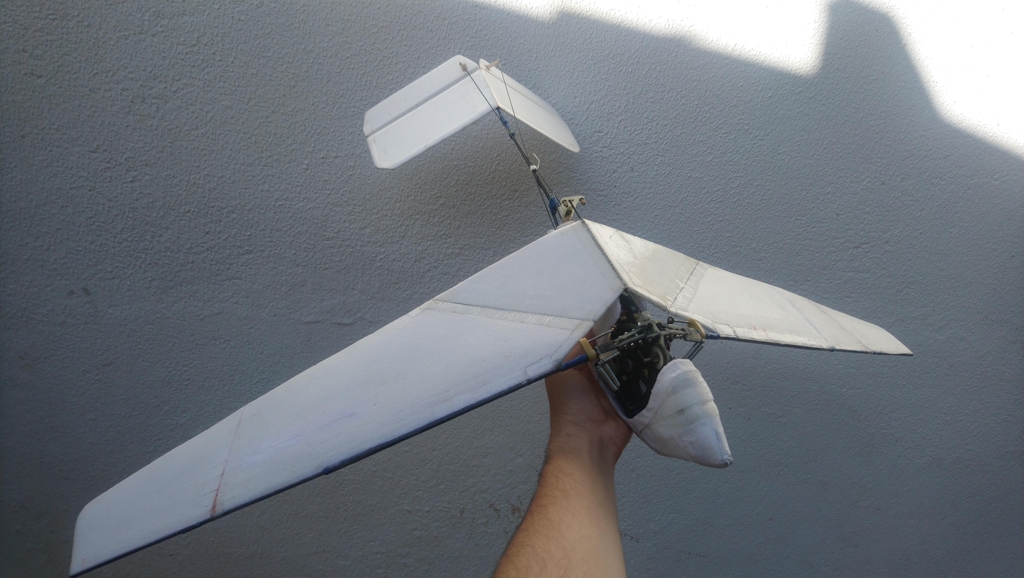
The completed ornithopter looked much more streamlined with the cowling
The cowling had a multitude of effects. For one, it was noticed that the aircraft would fly significantly faster when allowed to accelerate for a prolonged period of time in level flight. The aircraft would also lose energy less quickly during sudden maneuvers like rapid climbs and sudden turns. Oddly enough, the rate of climb didn’t seem to be affected. However, the model did seem to fly longer as the motor was not as hot at the end of a flight.
Video 6. Aerodynamic cowling placed round the fuselage
Conclusion
The final ornithopter configuration was capable of flying significantly faster than its original iteration and while also climbing better despite being much heavier. These changes indicated a clear improvement in the design of the wings, which could then be transplanted over to a servo-driven ornithopter with a much weaker and less efficient reciprocating drive. However, it was noted that the inertia of the wings played a very large role in the efficiency of the ornithopter. Unfortunately, only a small fraction of the energy imparted into accelerating the wings is ultimately recuperated by the crank mechanism. This constant energetic drain can be a very significant fraction of the overall power used by the aircraft. See the following paper:
PDF: The Moment of Inertia of Bird Wings and the Inertial Power Requirement for Flapping Flight
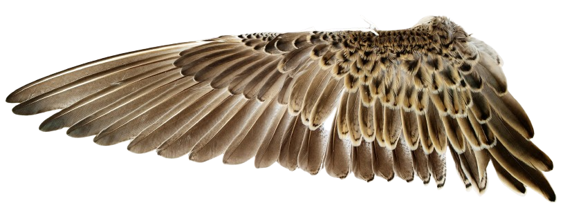
Bird wings have very low moments of inertia
It was calculated that the active twist design wasted roughly 30% of its input power just oscillating the wings. This serves as a warning that inertial losses must be factored in to make an efficient wing design. It is critical that the inertia of the wings is minimized such that the energy loss is as low as possible. Otherwise, the efficiency of the ornithopter will be low compared to other aircraft.
Arduino Code
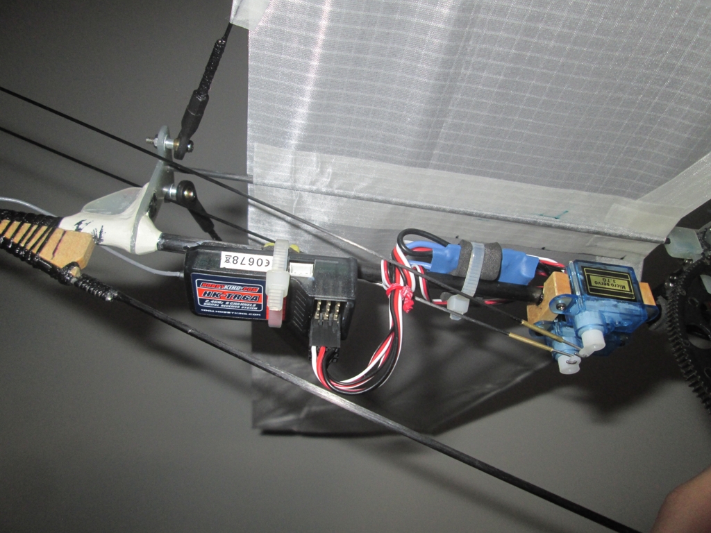
To allow the motor-driven ornithopter to glide, it was necessary to develop a system that could move the wings to an acceptable dihedral angle. A simple solution is to use a sensor connected to the motor via a circuit that creates a feedback loop, such that the motor stops in a particular location whenever the sensor is active. Once the wings reach their target location, an additional mechanism has to keep the wings in place. This can either be a mechanical lock, or alternatively, a set of downstroke springs which prevent the wings from collapsing during a glide. To accomplish the required feeback, an Arduino Nano was used in conjuction with a hall sensor to control the motor.
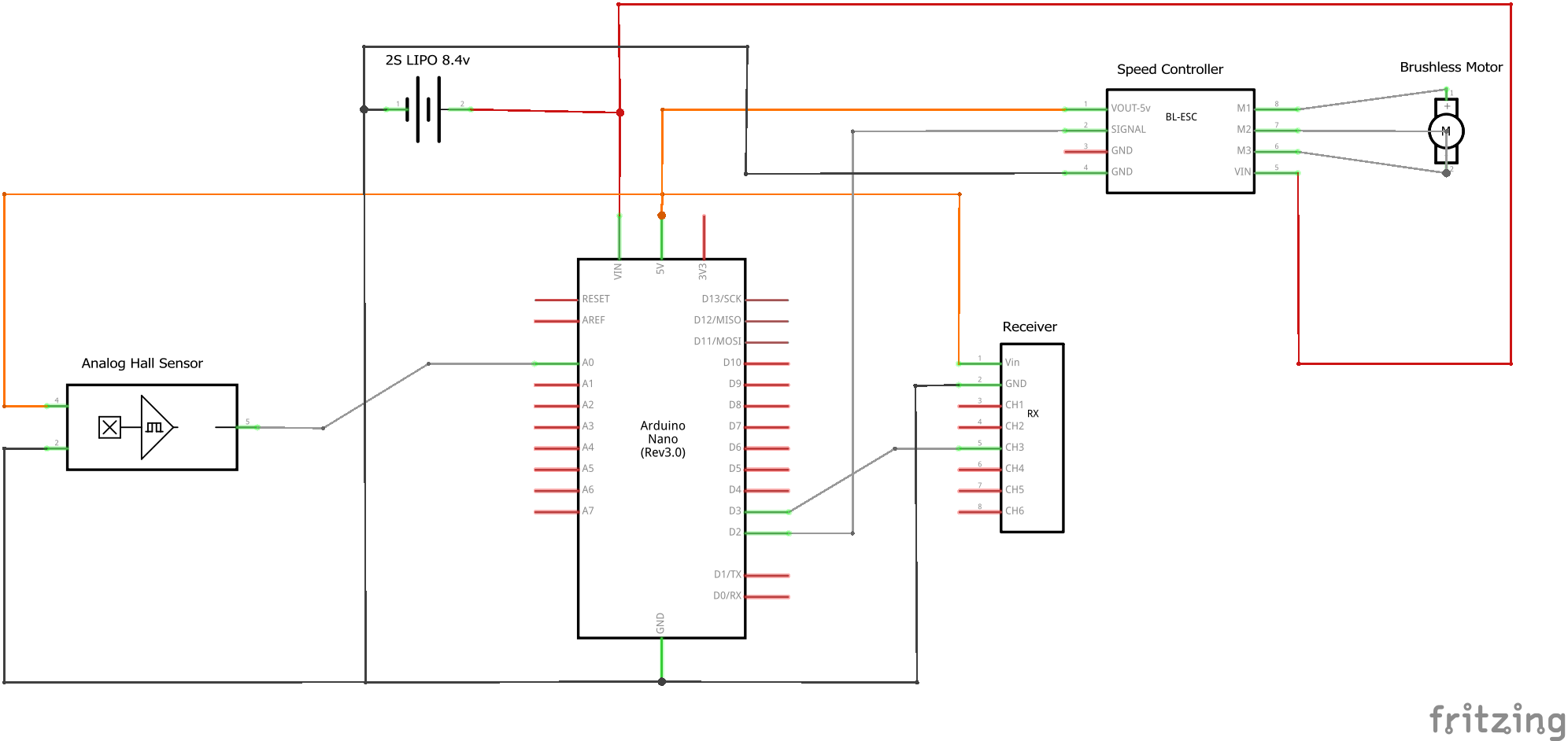
The sensor looks for a magnet attached to the crank, and once the magnet is infront of the sensor, the motor will turn off. Unfortunately some electronic speed controllers respond with a delay to throttle commands. In practice this means the crank will stop at the wrong position. To work around this one can run the motor for a short time interval after the magnet passes the sensor. If this delay is tuned correctly the crank will stop in the desired position. The arduino was programmed to only the behavior of the motor at low throttle settings, and beyond a particular threshold, it simply passed through the signal sent from the radio receiver. We can see the glide-lock system working in this video:
Video 7. Operation of the glide lock system
Github Repository: GlideLock